
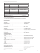
User Manual


0000
PASSW.
Txt 1
0000
9999
NO
ADV.SET
Txt 2
NO
YES
1 21 2
*1
10.4 mA
%
40.0
YES
ADV.SET
Txt 2
NO
YES
1 2
VOLT
IN TYPE
Txt 3
CURR
VOLT
1 2
33
3
3
3
*0
0-5
I.RANGE
Txt 4
0-5
0-2.5
0-1
0-0.5
CUST
1 2
3
3
0-230
V.RANGE
Txt 5
1 2
12
230
IN.HI
Txt 49
300
0.00
1 2
3
0.00
IN.LO
Txt 48
300
0.00
1 2
*7 *9 *7 *8 *9
0-300
0-230
0-120
0-5
0-2.83
0-1
0-0.5
CUST
3
3
20 4179V100-UK
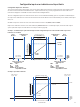
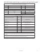
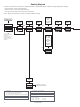
Routing diagram
If no key is activated for 1 minute, the display will return to the default state 1.0 without saving configuration changes.
1 Increase value / choose next parameter
2 Decrease value / choose previous parameter
3 Save the chosen value and proceed to the next menu
Hold 3 Back to previous menu / return to menu 1.0 without saving.
Continued on the page
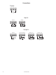
Routing diagram ADV.SET
*0
Default state.
Line 1 shows the scaled process value - OK or error.
Line 2 shows the selected engineering unit.
Line 3 shows analogue output or TAG no.
Line 4 shows status for communication and signal trending.
*1
Only displayed if password is enabled.
*7
Only displayed if CUST is selected!
This menu will change range automatically.
Power up
*8
Value will be forced to be greater than xx.LO.
*9
Maximum and minimum value selectable from menu must be
based on input type
VOLT: Min: 0.000 Max: 300
CURR: Min: 0.000 Max: 5.00
1 and 2 held:
Toggle line 3 function
A.Out / TAG.
(Setting is volatile - use
DISP setup menu to
change and store line 3
function).
Correct No
Yes
VOLT
CURRCorrect No
Yes