
User Manual


18 4179V100-UK
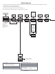
Configuration / operating the function keys
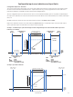
Documentation for routing diagram.
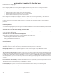
In general
When configuring the 4179, you will be guided through all parameters and you can choose the settings which fit the
application. For each menu there is a scrolling help text which is automatically shown in line 3 on the display.
Configuration is carried out by use of the 3 function keys:
1 will increase the numerical value or choose the next parameter
2 will decrease the numerical value or choose the previous parameter
3 will save the chosen value and proceed to the next menu
When configuration is completed, the display will return to the default state 1.0. Pressing and holding 3 will return to the
previous menu or return to the default state (1.0) without saving the changed values or parameters.
If no key is activated for 1 minute, the display will return to the default state (1.0) without saving the changed values or
parameters.
Further explanations
Password protection: Programming access can be blocked by assigning a password. The password is saved in the device in
order to ensure a high degree of protection against unauthorised modifications to the configuration. Default password 2008
allows access to all configuration menus.
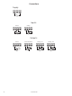
Signal and sensor error indication via display front 4511/4501
Error indication is displayed in line 1 as text and at the same time the backlight flashes. A flashing bullet in line 4 is indicating
correct functioning of 4511/4501.
Signal and sensor error indication without display front
Status of the unit can also be read from the red/green LED in the front of the device.
Green flashing LED 13 Hz indicates normal operation.
Green flashing LED 1 Hz indicates loop error.
Steady green LED indicates internal error.
Steady red LED indicates fatal error.
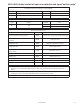
Advanced functions
The unit gives access to a number of advanced functions which can be reached by answering “Yes” to the point “ADV.SET”.
Memory (MEM): In the memory menu you can save the configuration of the device in the 4511/4501, and then move the
4511/4501 onto another device of the same type and download the configuration in the new device.
Display setup (DISP): Here you can adjust the brightness contrast and the backlight. Setup of TAG numbers with 6
alphanumerics. Selection of functional readout in line 3 of the display - choose between readout of analogue output or tag no.
Two-point process calibration (CAL): The device can be process-calibrated in 2 points to fit a given input signal . A low input
signal (not necessarily 0%) is applied and the actual value is entered via 4511/4501 Then a high signal (not necessarily 100%)
is applied and the actual value is entered via 4511/4501. If you accept to use the calibration, the device will work according to
this new adjustment. If you later reject this menu point or choose another type of input signal the device will return to factory
calibration.
Process simulation function (SIM): In the menu point “EN.SIM” it is possible to simulate an input signal by means of the arrow
keys and thus control the output signal up or down. You must exit the menu by pressing 3 (no time-out).
The simulation function exits automatically, if the 4511/4501 is detached.
Password (PASS): Here you can choose a password between 0000 and 9999 in order to protect the unit against
unauthorised modifications to the configuration. The unit is delivered default without password.