
User Manual


4179V100-UK 11
Accuracy, the greater of general and basic values:
of span = of selected standard range
* For custom signals, general accuracy and EMC specifications are 0.3% of full scale
Input specifications:
Current input:
Signal range. . . . . . . . . . . . . . . . . . . . . . . . . . . . . . . . . . . . . . . 0...5 AAC / 40...400 Hz
Maximum input limit. . . . . . . . . . . . . . . . . . . . . . . . . . . . . . . . . . 6.00 AAC @ 40°C
Programmable measurement ranges . . . . . . . . . . . . . . . . . . . . . . . . 0...0.5, 0…1, 0…2.5 & 0...5 AAC
Custom configurable signal range . . . . . . . . . . . . . . . . . . . . . . . . . . 0….5 AAC / 40...400 Hz
Min. span . . . . . . . . . . . . . . . . . . . . . . . . . . . . . . . . . . . . . . . . 0.5 AAC
Input resistance . . . . . . . . . . . . . . . . . . . . . . . . . . . . . . . . . . . . Nom. < 0.07 Ω
Voltage input:
Signal range. . . . . . . . . . . . . . . . . . . . . . . . . . . . . . . . . . . . . . . 0...300 VAC / 40...400 Hz
Programmable measurement ranges . . . . . . . . . . . . . . . . . . . . . . . . 0...0.5, 0...1, 0...2.83, 0…5, 0…120, 0…230 &
0…300 VAC
Custom configurable signal range . . . . . . . . . . . . . . . . . . . . . . . . . . 0...300 VAC / 40...400 Hz
Min. span . . . . . . . . . . . . . . . . . . . . . . . . . . . . . . . . . . . . . . . . 0.5 VAC
Input resistance . . . . . . . . . . . . . . . . . . . . . . . . . . . . . . . . . . . . Nom. 3 MΩ || 100 pF
Configurable input limits:
Configurable input limits, low:
VOLT . . . . . . . . . . . . . . . . . . . . . . . . . . . . . . . . . . . . . . . . . . 0 VAC to ‘Minimum selected input’
CURR. . . . . . . . . . . . . . . . . . . . . . . . . . . . . . . . . . . . . . . . . . 0 AAC to ‘Minimum selected input’
Configurable input limits, high:
VOLT . . . . . . . . . . . . . . . . . . . . . . . . . . . . . . . . . . . . . . . . . . ‘Maximum selected input’ to 300 VAC
CURR. . . . . . . . . . . . . . . . . . . . . . . . . . . . . . . . . . . . . . . . . . ‘Maximum selected input’ to 5 AAC
Input limit low/high, error indication levels:
UP . . . . . . . . . . . . . . . . . . . . . . . . . . . . . . . . . . . . . . . . . . . See table on page 14
DOWN . . . . . . . . . . . . . . . . . . . . . . . . . . . . . . . . . . . . . . . . . See table on page 14
ZERO. . . . . . . . . . . . . . . . . . . . . . . . . . . . . . . . . . . . . . . . . . See table on page 14
NONE . . . . . . . . . . . . . . . . . . . . . . . . . . . . . . . . . . . . . . . . . See table on page 14
Hysteresis. . . . . . . . . . . . . . . . . . . . . . . . . . . . . . . . . . . . . . . . 0.5% of ‘Max. output’
Error detection release delay . . . . . . . . . . . . . . . . . . . . . . . . . . . . < 2.5 s
Current output specifications:
Active unipolar and bipolar mA:
Programmable ranges . . . . . . . . . . . . . . . . . . . . . . . . . . . . . . . . . 0...20, 4...20, S4...20, ±10 and ±20 mA
Direct or Inverted action
V-curve function, 100-0-100% . . . . . . . . . . . . . . . . . . . . . . . . . . . 20-0-20 mA
Load. . . . . . . . . . . . . . . . . . . . . . . . . . . . . . . . . . . . . . . . . . . . ≤ 800 Ω
EMC - immunity influence. . . . . . . . . . . . . . . . . . . . . . . . . < ±0.5% of span*
Extended EMC immunity:
NAMUR NE 21, A criterion, burst . . . . . . . . . . . . . . . . . . . . < ±1% of span*
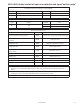
General values
Input type Absolute accuracy Temperature coecient
All ≤ ±0.3% of span* ≤ ±0.01% of span* / °C
Basic values
Input type Basic accuracy Temperature coecient
Current 1.5 mA 50 µA/ °C
Voltage 1.5 mVAC 50 µVAC /°C