Preh Touch Commander and Preh Screen Commander User Manual and Technical Data MC15T5
Table of Contents i. Model with multimedia base ________________________________________ 4 Ii. Model with VESA bracketry for pole or wall mount _____________________ 5 iii. Model number define _____________________________________________ 6 Ii. Model with VESA bracketry for pole or wall mount _____________________ 52 ii. Model with VESA bracketry for pole or wall mount _____________________ 4 iii. Model number define: _____________________________________________ 5 1.
i. Model with multimedia base LC-Display (15”) with touch interface or monitor glass swinging direction loudspeaker ON/OFF switch Pict. 1: front view serial connector RS 232 (touch controller) Pict. 2: rear view supply voltage connector (main power) MSR PS/2 Cable VGA connector audio cable Pict. 3: bottom view 3 subject to change without prior notice Preh KeyTec GmbH, www.preh-keytec.com 05.
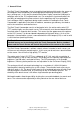
ii. Model with VESA bracketry for pole or wall mount LC-Display (15”) with touch surface or monitor glass MSR PS/2 VGA connector (15 pol.) Power Supply (jack bush) serial connector RS 232 (Touch Controller) Loud speaker Audio In Menu/Left Menu/ Right On/Off + Plus - Minus Pict. 4: front view Bracketry Threaded bushings (M5) Pict. 5: rear view II (bracketry) 4 subject to change without prior notice Preh KeyTec GmbH, www.preh-keytec.com 05.
iii. Model number define: LCD Size LCD-Type (TFT) Touchtechnology System MSR Speaker Color Accessories MC15T5xxM3Myy 15” Partner Tech Corp. 15 T5 Resistive(Both GS and CB) Only Protective Glass(for CB only) Multimedia Wallmount TK 1+2+3 Speaker White Black VGA-cable VGA-cable & RS232-cable power supply + GM power cord Ext.
1. General Points The Preh Touch Commander serves as graphical input device which makes the screen of the computer react immediately on touching graphical operating characters (symbols, keys, printings etc.). In this way the touchscreen allows simple, interactive handling of a computer even for the PC-inexperienced user. For example this input media offers the possibility of reducing training time and costs for the operating staff via a comfortable user's dialogue.
The Preh Touch / Screen Commander can also be used with optional VESA bracketry for wall mount hardware. Pict. 6: Example for adjustable Wall mount solution 2. Contents of packing Prior to operating your Preh Touch / Screen Commander, please check whether the following parts are included and are in undamaged condition: 1 Preh Touch Commander or Preh Screen Commander 1 CD-Rom with touch driver for the operating systems DOS, Windows 3,1x/9x/NT/2000 XP and OS/2.
3. Installation of Touchscreen Please read the following instructions prior to starting to use the Preh Touch / Screen Commander! The following steps are necessary for a correct function of the device: 1 Adjust your computer for the proper video resolution [1024x768 / 60 Hz] and switch it off, connect Touch / Screen Commander, switch on computer and Touch / Screen Commander (see chapter 3.2). If you are asked for confirming the new hardware "standard monitor", confirm according to display instructions.
3.3 On Screen Display (OSD) For setting the LC Display you find 5 buttons on the front of the housing (see pict. 10). LED 2 6 3 5 1 4 Pict. 7: Description of the buttons for perating the On Screen Display. 1. Power Switch Pressing this button turns the display system power on or off. When the power switch are switch on, this LED lights in green. The LED indicates the different power status with altered LED colors when monitor operates in different modes 2.
3.3.1 OSD Control The LCD monitor can easily adjust the features of displayed image and the buttons in the front of the LCD monitor can do the adjustments. When using these controls, OSD menu will display the changed on the screen. OSD MENU - AUTOTUNE Press menu/Left or menu/Right call menu then press „+“ to make LCD monitor adjust the related parameters automatically for optional display status. Important note to menu point AUTO TUNING Most video cards differ in regard to their video signals output.
- CONTRAST Adjust the contrast using + and - button. Contrast - + 50 - CLOCK Adjust the clock using + and - button. Clock - + 50 - PHASE Adjust the phase using + and - button. Phase - + 50 - H-POSITION (HORIZONTAL POSITION) Pressing + moves the display image to the right; Pressing - moves the display image to the left. H-Position - + 50 - V-POSTION (VERTICAL POSITION) Pressing + moves the display image to the upware; Pressing - moves the display image to the downware.
- OSD V-POSITION (OSD VERTICAL POSITION) Pressing + moves the OSD image to the upware; Pressing - moves the OSD image to the downware. OSD V-Position - + 50 - VOLUME Adjust the volume using + and - button. Volume - + 50 - RED COLOR Adjust the values of red color gain using + and - button. Red Color - + 50 - GREEN COLOR Adjust the values of green color gain using + and - button. Green Color - + 50 - BLUE COLOR Adjust the values of blue color gain using + and - button.
- FACTORY RESET Press the + button to restore Volume, OSD V-Position, OSD H-Position, V-Position, HPosition, Phase, Brightness, Clock to factory default. Factory Reset + Yes - No 3.4 Mechanical Adjustment of the LCD Position The LCD position on a VESA Mount Preh Touch / Screen Commander cannot be changed directly at the Product. The adjustment (tilting or swinging) of the Touch Screen Commander depends on the pole or wall mount hardware used.
Note: On changing the housing position you should be careful to not get your fingers too near to the opening on the rear side of the housing as they might get pinched there. 4. Driver Installation Important Note: A new calibration is always necessary if another touchscreen was connected to the computer or if the screen resolution was changed.
6.2 Troubleshooting list A lot of malfunctions can be traced back to incorrect or loose cable connection. So please make sure that all plug connections are correct and secured.
7. Technical Data 7.1 Product Specification Configuration LCD Display Display Size Pixel Pitch Max. Resolution Contrast Ratio Brightness Response Time Display Color Viewing Angle MC15T5XXM3MX 15” TFT active matrix panel 304(H)x228(V) mm 0.297(H)x0.297(V) mm XGA 1024x768 350:1 250 cd/m2 6/17 ms 262,144 L/R 60∘ ~ 60∘ U/D 40∘ ~ 60∘ Swivelling 39∘ +/- 3∘ Tilt PC Interface 40∘ +/- 3∘ RGB analog 0.
7.2 Electronics: Following specifications are for the multimedia model only: Line voltage: Power consumption 100-240 AC, 47-63 Hz, 0.6A max. 20 W Following values are valid for the model VESA mount bracketry only: Operating Voltage: 12 V ± 5% (100-240VAC, 47-63Hz, 2.2A) Ripple: < 120 mV Power Consumption max. 30W The values in brackets are for the power supply delivered with the Touch / Screen Commander.
7.5 MSR (Option) Interface: Track: Decode: Scan direction: Power Supply: Power consumption: Durability: Card Spec: Reading Track Width: Card Feeding Speed: PS/2 key. Three Tracks KB Interface. Right Side scan. 5V DC ±5% Less than 20mA 500,000 cycle. ISO7811 1.5mm 10 ~ 120 cm/sec(4-50inch/sec) 7.6 Audio Amplifier Controller: Output: Power: Control Method: Frequency: TDA7496L 2W/Ch. 12V/25mA PWM Adjust. 20 ~ 20KHz 7.
7.9 Environmental conditions Operating amibent temperature: Storing temperature: Relative humidity of air: Air pressure: 0°C...50°C -20°C...60°C 10%...90% (at max. 35°C) 700hPa...1060hPa 8. Safety issues Please read these instructions carefully before connecting the unit to any AC-mains and keep the instructions also for later use. The multimedia type is belong to Class I type and the wall mount type is belong to Class III type for power consuming configuration.
9. Further Information All Preh products are subject to a continuous process of improvement. For this reason we reserve the rights of technical modifications. We point out that inadequate handling, storage, influence and/or modification can cause disturbances and damage in usage. In case you modify our products in any way we do not assume warranty and liability unless you have an explicit release in writing for your specific case. This applies especially to unprofessional repair and maintenance jobs.
12. FCC Warning Statement Note: This equipment has been tested and to comply with the limits for Class B or Class A digital device, pursuant to Part 15 of the FCC Rules. These limits are designed to provide reasonable protection against harmful interference in a residential installation. This equipment generates, uses and can radiate radio frequency energy and, if not installed and used in accordance with the instructions, may cause harmful interference to radio communications.