
TPM3 for 3 Kaneka Modules Assembly Instructions

CAUTION:
Do not attempt to
remove the Pivot
Bolt during tilt
adjustments!
Removal could
lead to serious
personal injury or
death. Adjustments
are made with the
Pivot Bolt
hardware loosened
but in place.
CAUTION:
This is a two
person activity. As
the Pivot Bolt is
loosened and the
Support Bar
hardware is
removed, the rack
is heavy and
unstable. It must
be held in place
by one person
while the second
person loosens
and removes the
hardware and then
re-installs/tightens
the hardware back
in place. Failure to
do so could lead
to serious
personal injury
and damaged
components.
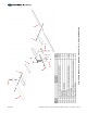
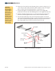
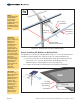
Figure 6-1: Preparing to Adjust the Tilt Angle
Loosen
Pivot Bolt
Remove
Support Arm
Hardware
(upper hardware only)
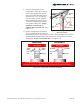
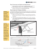
Elevation Set Points
Strongback
Support
Bar
65°55° 45° 35° 25° 15°
Figure 6-2: Positioning Support Bar
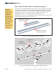
Step 5: Now return and tighten mounting hardware.
A. Return and tighten each set of the 3/8" mounting hardware, securing the
Module Rails to the Support Angles. Torque all at 32-34 ft.-lbs.
B. Return and tighten each set of 1/4" mounting hardware, securing the PV
Modules to the Module rails. Torque all at 6-8 ft.-lbs.
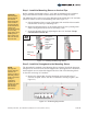
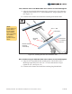
Step 6: Adjust the Tilt Angle of the Rack
To adjust the tilt angle, loosen the Pivot Bolt hardware and remove the Support Arm
upper hardware attaching the Support Arm to the Strongback. Use great care in this
procedure as it can be dangerous if the procedure is not completed as described with
a minimum of two people. (See Figure 6-1)
A. While one person holds the south edge of rack, the other loosens the Pivot
Bolt and removes the upper 3/8" hardware attaching the Support Bar to the
Strongback.
B. Tilt the rack to the desired elevation angle (15°, 25°, 35°, 45°, 55° or 65°)
and re-attach the Support Bar to the Strongback, placing the 3/8" hardware
in the appropriate hole matching the desired elevation. Torque to 32-34 ft.-
lbs. (See Figure 6-2)
Assembly Instructions, Top-of-Pole Mount (TPM3) One over Two (Version 1, Rev A) 9 of 10