Top-of-Pole Mount for 3 Kaneka Modules (TPM3) One over Two ASSEMBLY INSTRUCTIONS step-by-step assembly and installation Version 1, Rev A SP3307-2 PCN 021513-1
Top-of-Pole Mount for 3 Modules (TPM3) One over Two A few words about the product The TPM3 One over Two is designed to mount on 4 inch SCH40/80 galvanized steel pipe (installer supplied). Pipe size and foundation requirements are based on several factors including the array surface area, maximum design wind speed, exposure category, soil type, steepest expected tilt angle, and above-ground clearance.
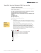
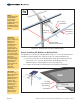
6 5 7 8 Top-of-Pole Mount for 3 Modules One over Two, Parts Identification 4 2 3 2 9 1 2 of 10 Assembly Instructions, Top-of-Pole Mount (TPM3) One over Two (Version 1, Rev A)
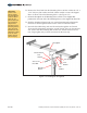
Step 1: Install the Mounting Sleeve on Vertical Pipe CAUTION: Use care while working around the structure during assembly. There could be components that create hazards or obstruct free movement causing serious bodily injury. Many are at head/eye level. Move slowly and with care around the work area. Before installing the Mounting Sleeve, verify that the Mounting Pole is plumb to the ground and hasn't shifted or leaned while the concrete footing has cured.
CAUTION: This is a two person activity. The Strongback must be held in place by one person while the second person aligns it and secures it to the Mounting Sleeve using the Pivot Bolt and the 1/2" hardware. Failure to do so could lead to serious personal injury. B. Remove the Pivot Bolt from the Mounting Sleeve and also collect the 3/8" x 1-1/4" bolt, nut, flat washers and lock washer needed to secure the Support Bar to its Pivot Tab on the Mounting Sleeve. (See Figure 2-2) C.
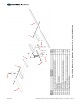
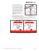
F. Pivot the Strongback and the Support Bar to align the mounting holes of the Support Bar with the Pivot Tab on the Mounting Sleeve. Insert the 3/8" x 1-1/4" bolt and one flat washer thru the Support Bar and Mounting Tab and secure it with the remaining flat washer, lock washer and hex nut. Torque hardware on both ends of Support Bar at 32-34 ft.-lbs. (See Figure 2-3) Support Bar 3/8" Hex Nut Pivot Tab 3/8" x 1-1/4" Bolt Lock Washer Flat Washers Figure 2-3: Securing Support Bar to G.
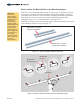
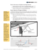
Step 3: Attach the Module Rails to the Mounting Angles CAUTION: This is a two person activity. Module Rails are unstable before they are fully secured to the Support Angles. Module Rails must be held in place by one person while the second person aligns and secures them to the Support Angles. Failure to do so could lead to serious personal injury. There are two sets of Module Rails; a short set and a long set. The short set mounts on the upper or northern end of the Strongback and holds one Module.
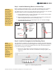
First, install the short set of Module Rails at the northern end of the Strongback A. Align the short Module Rail mounting holes with the holes of the Mounting Angle and secure with 3/8" x 1" bolts and hardware. Finger-tighten for now. (See Figure 3-3) B. Continue in this manner and install the remaining short Module Rail. N W E S NOTE: Finger-tighten the Module Rails to the Strongback while installing. After PV Modules are installed, re-tighten to specified torque values.
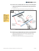
N W E S NOTE: Finger-tighten the Module Rails to the Mounting Angles while installing. After the Modules are installed, re-tighten to specified torque values. 3/8" x 1" Bolt Flat Washer Flat Washer Mounting Angle Lock Washer 3/8" Nut CAUTION: This is a two person activity. PV Modules are heavy and unstable before they are fully secured to the Module Rails. PV Modules must be held in place by one person while the second person aligns and secures them to the Module Rails.
Step 5: Now return and tighten mounting hardware. A. Return and tighten each set of the 3/8" mounting hardware, securing the Module Rails to the Support Angles. Torque all at 32-34 ft.-lbs. B. Return and tighten each set of 1/4" mounting hardware, securing the PV Modules to the Module rails. Torque all at 6-8 ft.-lbs. Step 6: Adjust the Tilt Angle of the Rack CAUTION: Do not attempt to remove the Pivot Bolt during tilt adjustments! Removal could lead to serious personal injury or death.
C. Re-tighten the Pivot Bolt. After changing the tilt angle and tightening the Support Bar hardware, the Pivot Bolt must be re-tightened. The Pivot Bolt cannot be left loose - the Mounting Sleeve Vertical Towers must be firmly clamped to the sides of the Strongback eliminating any gaps between the Vertical Towers and the Strongback. Torque to 125-150 ft.-lbs.
Albuquerque Office 1700 Louisiana Blvd., Suite 130 Albuquerque, NM 87110 Telephone: 800.260.3792 Fax: 505.889.3548 www.preformed.com E-mail: info@plpsolar.