
MPM-G2 Assembly Instructions


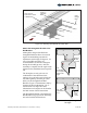

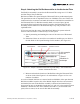
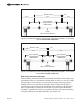

Table Of Contents

Step 4: Attaching the Rail Set Assemblies to the Horizontal Tube
Each Rail Set Assembly is secured to the Horizontal Tube using two 1/2" L-Bolts
and four Flange Nuts per Rail Set.
Rail Set Assemblies are spaced along the Horizontal Tube in predetermined spans.
The span between each is dependent on the size of Modules to be used. Follow the
instructions below to measure and mark the locations of the Rail Set Assemblies on
the Horizontal Tube. If a Rail Set Assembly lands on or near a Pipe Cap and
prevents the Pipe Cap from being properly secured to the Horizontal Tube, the
Assembly must be shifted to work around the Pipe Cap. This procedure is also
explained below.
It is best to start from the center of the Multi-Pole Mount-G2 system and work
outward. This will ensure a centered array over the system.
A. Start by measuring and marking the center of the entire run of Horizontal
Tube.
B. Determine if there are an odd or even number of modules per row. Refer to
the title block of the Layout Drawings for this number. (See Figure 4-1)
Figure 4-1: Sample Title Block from PLP Layout Drawing - Use to determine
number of Modules Per Row
Sets of Modules
Total Modules
Number of Rows
In this example
there are:
7 Sets of
4 Modules in
Landscape
C. Measure and mark the locations of the Rail Sets along the Horizontal Tube
as shown in the either Figure 4-2 for odd numbers or Figure 4-3 for even
numbers of modules.
As a rule-of-thumb, Rail Sets are centered under each Module with a span between
Rail Set Assemblies equal to 60% of the Module length. Once these are measured
and marked, the next-in-line Rail Set Assembly is measured and marked using a
factor equal to 20% of the Module Length plus 1/2" (the 1/2" is the spacing between
Modules). Calculate the 20% factor, double it and add 1/2", the end result is the
span (center to center) for the next-in-line Rail Set Assembly.
Assembly Instructions, Multi-Pole Mount - G2 (Version 1, Rev D) 7 of 15