
MPM-G2 Assembly Instructions


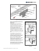

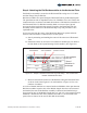
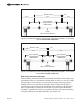

Table Of Contents

Figure 3-4 Attaching Rail Bracket to Power Rail
Attach the Strongback Bracket to the
Rail Bracket
Although the design of the Rail and
Strongback Brackets allows for nine tilt
angles accommodating seasonal tilt
adjustments (10 through 55-degrees), for
ease of assembly and safety, it’s
recommended to set the tilt at 0-degrees
during the assembly process. After the
assembly is complete, the tilt angle can be
adjusted to the installation/season specific
tilt.
The tilt angles are set by the use of a
combination of nine different clock
settings via seven holes (used to lock the
tilt) and originating from the pivot bolt
hole(s) of the Strongback and Rail
Brackets. Figure 3-5 demonstrates this by
showing the hole combination “3 & 5”
which creates a 0-degree tilt. More
information on tilt angles can be found in
the final section of these instructions.
The Strongback Bracket is attached to the
Rail Bracket using a pivot bolt and flange
nut and a lock bolt and hardware.
Align center of
Power Rail to center
of Rail Bracket
Center
of Rail
Bracket
5/16” x 1”
Carriage
Bolts
5/16
Flange
Nuts
"
South
Hole
combination
3 & 5 equals a
0-degree tilt
angle.
1
4
5
6
7
2
3
Hole
Combination
3 & 5
Pivot
Bolt
Holes
Pivot
Bolt
Holes
Figure 3-5: Setting a 0-degree
Tilt Angle
Assembly Instructions, Multi-Pole Mount - G2 (Version 1, Rev D) 5 of 15