
MPM-G2 Assembly Instructions


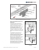

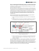
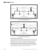

Table Of Contents

Step 3: Assemble the Rail Set
Assemblies
Rail Set Assemblies include a Power Rail,
Rail Bracket, and a Strongback Bracket
(See Figure 3-1).
Attach the Rail Bracket to the Rail
The Power Rail is secured to the Rail
Bracket using 5/16" x 1" carriage bolts and
flange nuts. Be certain to orient the Rail
Bracket to the Power Rail as shown in
Figure 3-2. In particular, take note on the
relationship of the Pivot Hole to the N-S
directions.
A. Along its length, measure and
mark the centers of the Power Rail
and the Rail Bracket. (See Figure
3-4)
B. Pre-load eight 5/16" x 1" carriage
bolts into the channels of the
Power Rail (four in the upper
channel and four in the lower
channel). (See Figure 3-3)
C. Mount the Rail Bracket onto the
eight carriage bolts aligning the
center mark on the Rail Bracket to
the center mark on the Power Rail.
Secure with flange nuts. Torque to
14-16 ft-lbs. (See Figure 3-4)
NOTE:
Be sure that the
Rail Bracket is
properly oriented
to the Power Rail.
CAUTION:
Use care while
working around
the structure
during assembly.
There could be
components that
create hazards or
obstruct free
movement causing
serious bodily
injury. Many are at
head/eye level.
Move slowly and
with care around
the work area.
Figure 3-2: Orientation of Power Rail
to Rail Bracket
Pivot
Hole
Rail
Bracket
South
Power
Rail
Note: The Rail Bracket does not attach to the
Power Rail at this location.
Figure 3-1: Rail Set Components
Rail
Bracket
Strongback
Bracket
Power
Rail
Power
Rail
5/16” x 1”
Carriage
Bolts
Figure 3-3: Pre-load Carriage Bolts
4 of 15 Assembly Instructions, Multi-Pole Mount - G2 (Version 1, Rev D)