
MPM-G2 Assembly Instructions

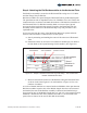
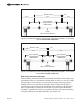


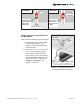


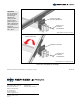
Table Of Contents

WARNING:
Do not attempt to
remove the Pivot
Bolt during tilt
adjustments!
Removal could
lead to serious
personal injury or
death. Adjustments
are made with the
Pivot Bolt
hardware loosened
but in place.
CAUTION:
This is a two
person activity. As
the Pivot Bolt is
loosened and the
Support Bar
hardware is
removed, the rack
is heavy and
unstable. The rack
must be held in
place by one
person while the
second person
loosens and
removes the
hardware and then
re-installs/tightens
the hardware back
in place. Failure to
do so could lead
to serious
personal injury
and damaged
components.
Step 6: Change the Tilt Angle of the Array
This procedure can be dangerous if it is not completed as described with a
minimum of two people so use great care. The process involves loosening the pivot
bolt and the temporary removal of the lock bolt. When the lock bolt is removed; the
rack becomes unstable and must be held in place by a second person.
As discussed in Step 3, the tilt angle is set by a specific hole combination which is
unique to the desired tilt angle. The hole combination is derived by a series of three
threaded holes in the Rail Bracket and four holes in the Strongback Bracket (see
Figure 6-1). For example, if a 40-degree tilt is desired, the hole combination would
be 2 & 7. The table in Figure 6-1 defines the nine possible tilt angles and their
respective hole combinations.
A. While one person holds the south edge of rack, the other loosens the Pivot
Figure 6-1: Determining Hole Combinations for Specific Tilt Angles
Rail Bracket
Strongback Bracket
1
2
3
Pivot
Bolt
Hole
4
5
6
7
Pivot
Bolt
Hole
Set Hole Combination Tilt Angle in Degrees
1 3 & 5 0 (used during assembly of rack)
2 2 & 4 10
3 2 & 5 20
4 1 & 4 25
5 2 & 6 30
6 1 & 5 35
7 2 & 7 40
8 1 & 6 45
9 1 & 7 55
Bolt and removes the 1/2” lock bolt and hardware from the Strongback
Bracket. (See Figure 6-2)
B. Tilt the rack to the appropriate hole combination matching the desired tilt
and re-install the 1/2” lock bolt and hardware, passing it through the
Strongback Bracket and into the threaded hole of the Rail Bracket. Torque
to 45-50 ft.-lbs.
C. Re-tighten the Pivot Bolt as the Pivot Bolt cannot be left loose. The Rail
Bracket and Strongback Bracket must be firmly clamped to one another
eliminating any gaps between them. Torque to 45-50 ft.-lbs.
14 of 15 Assembly Instructions, Multi-Pole Mount - G2 (Version 1, Rev D)