
MPM-G2 Assembly Instructions

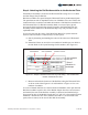
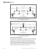


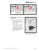

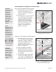

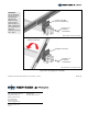
Table Of Contents

Installing Modules using RAD End and Mid Clamps:
Start with exterior Module and End Clamps.
A. Place Module on two Power Rails,
centering it lengthwise. Use a
square to square-up the Module to
the Power Rails.
B. Insert one 5/16” x 2, 2-1/4, 2-1/2 or
2-3/4” RAD bolt into the top slot
of the Power Rail. Push the bolt
against the side of the module
frame and twist to lock in place.
Install End Clamp onto bolt and
secure with 5/16" flange nut.
Torque to 14-16 ft.-lbs. (See
Figures 5-1 and 5-6)
Install next in-line Module using Mid Clamps.
C. Insert one 5/16” x 2, 2-1/4, 2-1/2,
or 2-3/4” RAD bolt (bolt length is
dependent on depth of Module
frame) into each Rail, next to the
previously installed exterior
Module. Twist RAD bolt to lock in
place. (See Figure 4-7)
D. Place next Module onto Rails.
E. Install a Mid Clamp onto each
RAD bolt making certain that the
Mid Clamp tabs rest between the
two modules.
F. Push Modules against Mid Clamp
tabs and secure Mid Clamp with
5/16” flange nut. Torque to 14-16
ft.-lbs. (See Figures 5-2 and 5-7)
Figure 5-6: Installing Modules using
RAD Hardware End Clamp
Figure 5-7: Installing Modules using
RAD Hardware Mid Clamp
Rotate
to Lock
Tabs
Push Modules
against Tabs
of Mid Clamp
RAD
Mid Clamp
5/16” x
RAD Bolt
**
5/16”
Flange
Nut
5/16 x 2, 2-1/4, 2-1/2, or 2-3/4 inch bolt.
Length dependent on Module frame depth.
**
Rotate
to Lock
P14 Power Rail
RAD
End Clamp
5/16” x
RAD Bolt
**
5/16”
Flange
Nut
5/16 x 2, 2-1/4, 2-1/2, or 2-3/4 inch bolt.
Length dependent on Module frame depth.
**
WARNING:
Be certain that all
Flange Nuts on
End and Mid
Clamps are
tightened and
torqued to the
stated values.
Failure to do so
could lead to
serious personal
injury and/or
damaged
components and
property.
WARNING:
The Tabs of the
Mid Clamps must
rest between the
Modules. Failure
to do so could
lead to serious
personal injury
and/or damaged
components and
property.
NOTE:
RAD Bolts must be
locked into the
channel by rotating
clockwise 90-
degrees. Use the
indicator slot on
the threaded end
to identify whether
or not the bolt has
been locked.
Indicator Slot
shown in Red
Locked
Assembly Instructions, Multi-Pole Mount - G2 (Version 1, Rev D) 13 of 15