
MPM-G2 Assembly Instructions

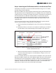
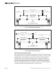


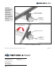
Table Of Contents

Figure 5-4: Pre-loading Standard Mid Clamp Hardware into Power Rail
D. Install a Mid Clamp onto each
carriage bolt making certain that
the Mid Clamp tabs rest between
the two modules.
E. Push Modules against Mid Clamp
tabs and secure Mid Clamp with
5/16” flange nut. Torque to 14-16
ft.-lbs. (See Figures 5-2 and 5-5)
Tabs
Pre-loaded
Carriage Bolt
Push Modules
against Tabs
of Mid Clamp
Standard
Mid Clamp
5/16”
Flange
Nut
Now install the next in-line Module using Mid Clamps.
C. Before placing the interior Module onto the Power Rails, first insert two
(one in each Power Rail channel) 5/16” x 2, 2-1/4, 2-1/2, or 2-3/4” carriage
bolts (bolt length is dependent on depth of Module frame) into the Module
Rail, sliding the bolts inward next to the previously installed exterior
Module. (See Figure5-4)
5/16 x 2, 2-1/4, 2-1/2, or
2-3/4 inch bolt. Length is
dependent on depth of
Module frame.
**
Insert 5/16" x
Carriage Bolts
into Power Rail
Slide Carriage Bolts
inward, adjacent
to Southern Module
**
Figure 5-5: Installing Modules using
Standard Hardware Mid Clamp
WARNING:
The Tabs of the
Mid Clamps must
rest between the
Modules. Failure
to do so could
lead to serious
personal injury
and/or damaged
components and
property.
NOTE:
If using standard
5/16” carriage
bolts for Mid
Clamps, the bolts
must be inserted
into the Power Rail
before installing
next in-line
northern Modules.
If using RAD
hardware, the
hardware can be
inserted anytime
at any position
along the
Power Rail.
12 of 15 Assembly Instructions, Multi-Pole Mount - G2 (Version 1, Rev D)