
MPM-G2 Assembly Instructions


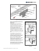

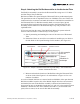
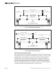

Table Of Contents

Attaching the Rail Sets to the
Horizontal Tube
A. Using a tape measure, mark the
pre-determined locations of the
Rail Sets on the Horizontal Tube
using the instructions outlined
above. (See Figure 4-5)
B. Place the Rail Set on top of the
Horizontal Tube, aligning it to its
mark made in Step A above.
C. From below, insert the two 1/2" L-
Bolts into the two holes of the Rail
Bracket guiding the opposite ends
into the two notches on the
opposite side of the Rail Bracket.
Loosely thread two 1/2" Flange
Nuts on each of the L-Bolts.
D. Continue to tighten the Flange
Nuts, alternating between the four
so the L-Bolts and Rail Bracket are
drawn evenly against the
Horizontal Pipe. (See Figure 4-6)
Torque all four to 45-50 ft.-lbs.
Figure 4-4: Repositioning a Rail Set to work around a Pipe Cap
Figure 4-5: Attaching the Rail Set to
the Horizontal Tube
WARNING:
This is a two
person activity,
because the Rail
Set is unstable
before it’s
secured. One
person should
steady the Rail
Set while the
other secures it.
Failure to do so
could lead to
serious personal
injury.
Pipe Cap
Shift the Rail Set
Assembly to work
around the
Pipe Cap
60% of Module Length
puts Rail Set on top
of Pipe cap
Note: Power Rails not shown for clarity.
Rail Set
Assembly
1/2
Flange
Nuts
"
1/2
Flange Nuts
"
1/2
L-Bolt
"
Align
center
to layout
Mark
Assembly Instructions, Multi-Pole Mount - G2 (Version 1, Rev D) 9 of 15