USA R Electronic Console with the Pulse Feature Owner’s Manual Assembly and Operation page 1
Safety Information Please review and observe the following safety guidelines when assembling and using the Precor 903/904 electronic console: Before beginning any fitness program, you should see your physician for a thorough physical examination. • Read the Owner’s Manual and follow all instructions. These instructions are written to ensure your safety and to protect the equipment. • Handle the Precor 903/904 electronic console with care. Do not drop the equipment.
Table of Contents Safety Information ........................................................... 2 Obtaining Service ........................................................ 2 Before You Begin .......................................................... 4 Unpacking the Electronic Console ................................ 4 Installing the Electronic Console ................................. 5 903 Assembly Procedures ........................................... 5 904 Assembly Procedures ..............
Before You Begin Thank you for purchasing the easy-to-use electronic console option for your Precor 903 Manual or 904 Total Body Treadmill. Before assembling the console onto your treadmill, take the time to read through this manual so that you are familiar with the contents of the package and the features on the electronic console. Obtain the appropriate tools before assembling the electronic console onto the 903 or 904 treadmill.
Installing the Electronic Console The handrail clamp can be used on either the 903 or 904 treadmill. However, the steps used to install the console onto the clamp are slightly different depending on which treadmill you have. Please refer to the steps that apply to your treadmill. 903 Assembly Procedures To install the 903 electronic console, take the following steps: 1. Locate the handrail clamp in the box that accompanies the electronic console’s box.
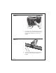
Diagram 2 3. Unlock and remove the mounting bracket from the back of the electronic console. Unlock the mounting bracket by pushing it down toward the base of the console. See Diagram 2. 4. Position the mounting bracket onto the handrail clamp so that the smooth side of the plate is facing you. See Diagram 3.
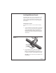
5. Secure the mounting bracket and clamp by inserting the two long screws through the mounting holes. You may need to squeeze the ends of the clamp together to install the screws. See Diagram 3. Tighten the screws into the recessed holes on the mounting plate using the Phillips head screwdriver. Do not over tighten the screws. A gap should remain between the opposite sides of the handrail clamp. 6. Unwrap the reed switch wire. Route the connector and wire through the hole in the handrail clamp.
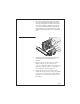
Diagram 5 9 0 R 9. USA 3 Attach the C clips around the handrail as shown in Diagram 5. Position the slight protrusion on the C clip around the reed switch wire and micro-adjustment knob cable. Squeeze the C clips together to close them and secure the wires in place. 10. With the electronic console successfully mounted, continue to Installing the Mounting Pads.
04 Assembly Procedures To install the 904 electronic console, take the following steps: 1. Remove the handrail clamp from its box. Take the long and short screws out of the handrail clamp using your fingers or a Phillips head screwdriver. Set the screws aside. 2. Position the handrail clamp over the right handrail’s micro-adjustment knob as shown in Diagram 6.
Diagram 7 C clamp 3. Insert the long screws through the mounting holes on the clamp. See Diagram 7. You may need to squeeze the ends of the clamp together to install the screws. Tighten the screws using a Phillips head screwdriver until the clamp remains securely in place. A gap should remain between the opposite sides of the clamp. See Diagram 7.
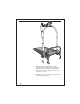
Diagram 8 7. Position the electronic console over the handrail clamp and plug the connector into the receptacle. See Diagram 8. Do not force the connection. The connector is designed to engage in one direction only. A tab on the connector and a slot on the receptacle help you determine the proper alignment. 8. Slide the electronic console onto the mounting bracket. It should “click” into place as you slide it toward the rear of the treadmill. 9.
Installing the Mounting Pads Two adhesive-backed foam pads (one thick and one thin pad) accompany your electronics option package. The thick pad is used as a spacer and you place the reed switch on it. The thin pad is positioned onto the flywheel and becomes the base for the magnet. CAUTION: Both pads require a 24-hour period to bond properly to the equipment. Do not operate the treadmill during this time.
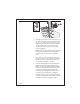
Diagram 10 Thic km oun ting pad 2. Remove the paper backing from one side of the thick pad and press the pad firmly in place between the roller guard and the deck of the treadmill. See Diagram 10. 3. Make a copy of the template shown in Diagram A. See Appendix A. Cut along the dotted lines. Carefully cut away the shaft section and the magnet mounting pad island. 4. Lay the template against the right flywheel. Use a pencil to mark the outline for the magnet mounting pad. Remove the template.
Diagram 11 5. Remove the paper backing from one side of the thin pad and press the pad firmly in place onto the flywheel. See Diagram 11. 6. To mount the magnet and reed switch continue with the steps below, Attaching the Magnet and Reed Switch. Attaching the Magnet and Reed Switch For the electronic console displays to operate properly, a magnet and reed switch need to be precisely installed. The magnet is mounted to the flywheel and the reed switch is placed on the side rail.
Diagram 12 1. Remove the paper from the adhesive strip on the flywheel’s foam mounting pad. 2. Wipe the back of the magnet with a dry clean, soft cloth. Position it over the foam mounting pad on the flywheel and press it onto the adhesive strip. Check that it is securely mounted. See Diagram 12. 3. Wipe the base of the reed switch (the “base” is the side opposite the ++) with a clean cloth.
Diagram 13 page 16 5. Remove the paper to expose the adhesive strip that is on the foam mounting pad. Press the reed switch onto the pad. Be sure that the reed switch is positioned so that the wires are easily routed up the handrail. See Diagram 13. 6. Rotate the flywheel by hand to make sure that the magnet and reed switch are secure and are not rubbing on each other or on the treadmill. Check that the reed switch wire is clear of the flywheel.
Using the Electronic Console The electronic console provides multiple features and an easyto-read LCD display that lets you review your progress as you work out. The three buttons on the console let you control what information you want to display. The features, TIME, SPEED, DISTance, and CALORies, appear sequentially while in SCAN mode or you can “select” and display one particular feature. See Diagram 14 below.
To hold on one particular feature, press the SELECT button while the feature (such as TIME) is being displayed. The icon stops blinking. To return to SCAN mode, press the SELECT button one more time. The electronic console automatically shuts off when the treadmill is not in use after approximately 4 minutes. CLEAR— resets the displays back to zero. You can also use the CLEAR button in conjunction with the SET button to predetermine the time or distance of your workout.
PULSE—shows your heart rate if you have attached and are using the ear clip. Refer to Choosing a Target Heart Rate. You can also set an alarm to indicate when you reach your target heart rate. CALORIES - shows the estimated total number of calories burned during your workout. Setting the Timer The timer lets you set the duration of your workout. When the selected amount of time is up, an alarm beeps for about 10 seconds. To set the timer, take the following steps: 1.
Setting the DISTANCE If you have a specific number of kilometers that you want to travel during your workout, use this feature. An alarm sounds when you reach the specified distance. To set the distance, take the following steps: 1. When DISTANCE is displayed, press the SELECT button. The icon stops blinking. 2. Press the CLEAR button to reset the display to zero. 3. Press the SET button to choose the distance that you want to travel. You can set distance in 0.5 increments and select up to 99.
Diagram 15 shows your recommended heart rate training zone which is calculated using your age and your maximum attainable heart rate. The chart is based on a resting heart rate of about 72 for males and 80 for females. The optimum training zone is between 65% and 80% of your maximum heart rate. For efficient aerobic exercise and to obtain significant cardiovascular benefits, work hard enough to keep your heart rate in this zone.
Note: The located in the upper left corner of the display begins to blink once a heart rate is detected. 2. When the (PULSE) icon is displayed, press the SELECT button. The icon stops blinking. 3. Press the CLEAR button (“OFF” appears on the display). 4. Press the SET button (“50” appears on the display). Continue to press the SET button (number increments in units of 5) until you reach your target heart rate. Your target heart rate should be the lowest number shown in the Heart Rate Training Zone.
Maintaining the Electronic Console Use a damp, clean cloth after every workout to wipe off any perspiration that might have fallen on the electronic console. Periodically, clean the electronic console using a cloth dampened with a mild dishwashing detergent solution. Rinse the solution off with a clean, damp cloth. Thoroughly dry the electronic console before using it. CAUTION: Do not immerse the electronic console in liquid.
Diagram 17 2. Disconnect the reed switch wire by gently pulling the connector out of the receptacle. See Diagram 17. 3. Remove the back of the electronic console by unscrewing the four Phillips head screws. See Diagram 18. Set the screws aside. 4. Use your finger to pull up on the battery holder and slide the battery out. You may want to use your screwdriver to help push the old battery out of its holder. Discard the batteries.
Diagram 19 + 5. Reinsert two fresh batteries. Remove the existing batteries from the unit and reinsert two fresh (A-76 type) alkaline batteries. The positive (+) side should be facing you. See Diagram 19. Note: All the LCD segments momentarily appear when the fresh batteries are installed. 6. Replace the back of the electronic console by inserting the four Phillips head screws back into place. Tighten the screws using the Phillips head screwdriver. 7. Reconnect the reed switch wire into the console.
page 26 Make a copy of this template or trace the pattern onto a different sheet of paper before cutting along the dotted lines.
Precor Incorporated P.O. Box 3004 Bothell, WA USA 98041-3004 USA R Precor is a registered trademark of Precor Incorporated. © 1996 Precor Incorporated. P/N 36834-102 Web version 9/98 Specifications subject to change without notice. 1-800-4-PRECOR NOTICE: Precor is widely recognized for its innovative, award winning designs of exercise equipment. Precor aggressively seeks U.S. and foreign patents for both the mechanical construction and the visual aspects of its product design.