
Instructions / Assembly

Step 3
If a stronger hold of the catch is required (e.g large/heavy door or door in drafty location), remove the 1st magnet assembly from top
of door and insert the power adjustment packers (supplied) as required into the bottom of the housing cup (underneath magnet)
therefore decreasing the gap between magnets (a gap less than 1/32" is not recommended). (fig 3)
Step 4
Once the desired level holding strength has been achieved, fit the (self-adhesive)
s/steel cover plates to the surface of the magnets (especially the visible
magnet/s)- to protect magnets from corrosion and to conceal the
magnet and screwhead from view, for a more seamless and
aesthetically pleasing finish. (fig 3)
Step 5
Fit the plastic door buffer into the door stop strip (or into door) to
reduce impact noise and bounce of door against jamb when
shutting. (fig 3)
Both door buffers (supplied) will be required for single door application - fitted
to top and bottom of the vertical door stop strip.
Note: to further reduce impact noise and bouncing effect when shutting door (especially when fitting the PLS24PRO
to a double door set), also fit the Poron Xrd foam pad (supplied) to the door stop strip.
(see the Poron info card inside the PLS24PRO package for fitting details).
door centre line
Precisi n
Step 2
Place the 1st magnet assembly into the hole in the door and screw into position (#2 phillips head screw driver required).
Place the 2nd magnet assembly into the hole in the jamb and screw into position.
Test operation of catch to make sure the door magnet is attracted to (not repelled away from) the jamb magnet.
Approx 2“ backset
DOOR
JAMB
Fig. 1
Fig. 2Fig. 2
jamb centre line (underside)
door stop strip
offset markoffset mark
Fig. 3
1/8 - 3/8 ˝
o 3/16´´
2nd magnet assembly
power adjustment
packers
cover plate
1st magnet assembly
DOOR
offset
JAMB
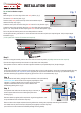
INSTALLATION GUIDE
Top of door installation example:
Step 1
Measure approx. 2" in from edge of door and mark position. (fig 1)
Transfer the mark onto the jamb. (fig 1)
Continue (both) mark points across top of door and underside of jamb
towards door stop strip. (fig 2)
Locate the centre point of the door along the mark and drill a 1/8" pilot hole. (fig 2)
Locate the centre point of the jamb along the mark, then offset that centre position by
approx. 1/8"- 3/8" (towards the door stop strip) and mark the new offset position. (fig 2)
Drill a 1/8" pilot hole into the jamb in the new offset position as marked.
Use the pilot holes as a guide to drill 2 x 15/16" diameter holes into door and jamb (to a depth of approx. 3/8") to accept magnet
assemblies. (fig 2)
(15/16" spade bit or Precision FB-23 forstner bit required).