
User Manual


7
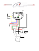
Wiring Diagram
IMPORTANT—The AMS-500 controls the pressure on the Waste Gate so the actual
boost level obtained is a combination of the Waste Gate Spring pressure and pressure
applied by the controller
www.nlrsystems.com or
Phone 334-741-71 00
OUT
EXH
IN
OUT
EXH
IN
Inc re a s e
Solenoid
Decrease
Solenoid
1/8 NPT
Plug
Air Supply or
Manifold Pressure
W astegate
Manifold Pressure
1 2
O
N
0
5
6
7
8
9
1
2
3
4
0
5
6
7
8
9
1
2
3
4
0
5
6
7
8
9
1
2
3
4
0
5
6
7
8
9
1
2
3
4
0
1
2
3
4
5
6
7
8
9
A
B
C
D
E
F
MAP S ensor port, 1/8 NP T threads. Install
desired fitting here and connect to Solenoids
and Wastegate as outlined below.
GROUND
Decrease Solenoid
Increase Solenoid
Ground
Solenoid +12 Volt
10 Amp Fuse
+12V Sw itched
Inp u t1
Inp u t2
Connect to +12V
or Ground.
+12 Volt
Do NOT Install Plug
Use proper wrench when installing
pre s su r e lin e fittin g !