
User Manual


2
Table of Contents
Configure AMS-500 Operating Mode Page 3
Configure Stage1 / Input1 Operating Mode Page 4
Setting Input1 and Input2 Activation Polarity Page 5
Setting Stage1 Boost Level Page 5
Setti ng S t a ge2 Boost Level and Ra m p Rat e Page 6
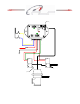
Wiring Diagram Page 7
Warranty Information Page 8
Notice—It is the responsibility of the purchaser to follow all guidelines and saf et y procedures
supplied with this product and any other manufactures product used with the AMS-500. It is
also the responsibility of the purchaser to determine compatibility of the AMS-500 with the
vehicle and other components.
NLR, LLC assumes no responsibility for damages resulting from accident, improper
installation, misuse, abuse, improper operation, lack of reasonable care, or all previously
stated reasons due to incompatibility with other manufacturer’s products.
NLR, LLC assumes no responsibility or liability for damages incurred from the use of
products manufactured or sold by NLR, LLC on vehicles used for competition racing.
NLR, LLC neither recomm ends nor approves the use of products manufactured or sold
by NLR, LLC on vehicles which may be driven on public highways or roads, and assumes no
responsibility for damages incurred from s uch use.
NLR, LLC does not recommend nor condone the use of its products for illegal street
racing.
Insta llation of NLR, LLC products s ignifies t hat you have read thi s doc um e nt and
agree to the terms stated w ithin.
Important Information:
Follow all recomm ended safety guidelines from this and other manufactures installation
guides. Static suppression ignition wires must be used with this unit! Mount the unit as far
away from secondary ignition components (coil, ignition wires, etc.) as physically possible.
IMPORTANT—The AMS-500 controls the pressure on the Waste Gate so the actual
boost level obtained is a combination of the Waste Gate Spring pressure and pressure
applied by the controller
www.nlrsystems.com or
Phone 334-741-71 00