
Hardware & BigComm Software Instruction Manual


BigStuff3 Pro SEFI System
Version 2.1 – February 2011 50
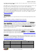
This capability is extremely important if the engine is fuel or spark sensitive at a given load and/or
RPM. For example, if the engine/transmission/rear gear combination makes the engine sensitive to
throttle changes at 2,200 rpm, the user can configure the X-axis in 200 or 300-RPM increments at or
around 2,200 RPM.
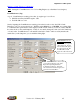
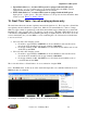
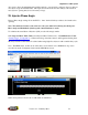
If the “Speed Density” control algorithm was selected during the aforementioned Hardware
Configuration step, the screen should show MAP (kPa) in the Y axis and RPM in the X axes. If the
screen shows TPS % and the preferred control algorithm is “Speed Density,” go back to
Main_Configuration
and select Seed Density instead of Alpha N.
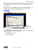
“Scaled” RPM inputs from this table define the RPM break points used in the follow
ing tables,
to name a few, which are described later in this manual!!!
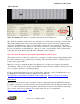
Dwell Time Table
Injector Phase Angle (degree) Table
Boost Spark (retard) Table
Starting Line Timing Table
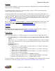
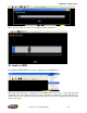
Y-Axis
X-Axis
Cell Number 16
Ce
ll 1
Scaled RPM Axis
(X- Axis)
Scaled Load Axis (Y-Axis)