
Hardware & BigComm Software Instruction Manual
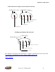

Switched 12V Source in the Vehicle
Foot brake or Trans-
brake Switch (12V
applied to this wire when
foot or trans-brake button
is depressed)
Brake
Lights or
Trans-
brake
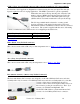
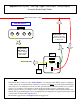
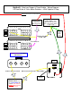
BigStuff3 - Data Log Trigger & Timer Enable - Wiring Diagram
Off Foot Brake & Trans-brake Switches – With Optional 2-Step
C DB
Boost Connector from Main
Wire Harness
A
Relay
86
30
85
87
87a
Wire used to Activate the “Timer Enable”
Ground
Optional Dash Mounted
ON/OFF Switch to turn
the “Timer Enable On
and Off. This Switch is
Required
with Optional
SR2 System
To Boost Connector Pin A
On/Off Switch
(required) for
Data Trgger wire
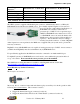
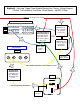
GEN3 ECU Header 2 - Terminals L - Y
Row 1
Row 2
Row 3
L M N P R S T W X Y
To Hdr 2, Y2
GEN3 ECU Header 1 - Terminals A - K
Row 1
Row 2
Row 3
A B C D E F G H J K
Yellow 2-Step Wire
To Hdr 1, B2