
Setup Tutorial Instruction Manual

12
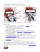
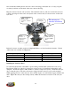
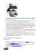
Type 6 - Using GM’s Oil Pump/Cam Sync Drive (P/N 1104068) Used in Conjunction
with BigStuff3’s 24 tooth Wheel. For standalone Coil-on-Plug (COP) systems.
Quick Setup Guide
1. Find TDC, cylinder number one (1), compression stroke. See Find_TDC on page 20.
2. Install the GM cam sync drive at TDC, then “bump” the starter until it engages the oil pump
drive while applying a light downward pressure. Make sure it is fully seated and tighten it
down.
3. Modify the Bigstuff3 main wire harness Cam connector, as described below, and connect the
harness to the GM cam sync drive. See GM_Cam_Sync_Wiring_Mods on page 12.
4. Find the falling edge from the Cam sync drive. See GM_Cam_Sync_Falling_Edge on page 15.
5. Roll the crankshaft forward (clockwise) 10
o
after the reading taken from the cam falling edge
test. For example, if the cam falling edge occurred at 2
o
before TDC (BTDC), roll the crank to
8
o
ATDC
6. Align the 2 wire crank sensor on any one of the teeth, on the BigStuff3 24 tooth wheel. Connect
purple sensor wire to red BS3 harness wire and the green sensor wire to the black BS3 wire.
See
LS1_2_Wire_Sensor_Connection for electrical connections if using an LS1 main harness.
7. Since we moved the crankshaft 8
o
after TDC (ATDC) subtract 8
o
from 360
o
(360
o
- 8
o
= 352
o
)
and input 352
o
into the COP Crank Reference input box (not the crank Trigger Crank
Reference box). Setting_the_LS1_Crank_Reference on page 28.
8. In the Operating Configuration window, input 24 into the Pulse Wheels cell for Crankshaft
(pulses/rev). See Setting_the_LS1_Crank_Reference on page 28.
9. Start the engine.
10. Use the “CamCrkAdv” window in the Dash to adjust the crank sensor so that the value
displayed in the “CamCrkAdv” window is 10. Tighten the crank sensor. See CamCrkAdv on
page 27.
11. With the engine still running, verify that the BigStuff3 “Dash” timing advance value equals the
timing value seen (with a timing light) at the crank. Change the crank reference value in the
COP Crank Reference input box (not the crank Trigger Crank Reference box), in the Operating
Configuration table, up or down, until the “Dash” value and the crank value are the same. See
Dash_Window on page 29.
12. Lastly, you will want to verify cam synchronization. See
Verifying_Synchronization on page.
The following section will explain more specifically how to install a camshaft synchronizer (cam
sync), and how to set it up for use with BigStuff3’s GEN3 COP Sequential Electronic Fuel System
(SEFI) system.
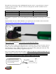
Using GM’s Cam Sync Drive
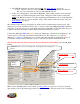
The BigStuff3 LS1 Cam connector will not plug directly into the GM Cam synch drive! The
connectors look similar, but they are different. The terminal pin letters (A, B & C) on the two
connectors are in opposite order, so the BigStuff3 LS1 Cam connector (not the terminals, so don’t cut
the wires!) will need to be removed from the harness and the connector identified below will need to
be installed.