GEN3 Powertrain Controller Ignition Setup Tutorial For Use with the GEN3 Pro SEFI Powertrain Systems February 2009 – Rev 1.
The installation and set-up of the following ignition configurations will be explained in this tutorial. For additional information on ignition systems, not listed below, refer to the GEN3 Pro SEFI System User’s Manual. Ignition Types Covered in This Tutorial 1. **Stand-alone IPU Distributor Only (Go to Type_1) 2. **Modified IPU Distributor (serving as the cam sync) with a Crank Trigger Setup (Go to Type_2) 3. **MSD Distributor Used to Only Distribute Spark from an MSD 6A/7A/8A,… box, with a Crank Trigger.
Type 1 - Stand-alone Distributor (no cam sync signal or crank trigger used) Stand Alone Distributor Overview A stand-alone IPU distributor can be used with the GEN3 Pro SEFI system for sequential fuel and spark control. “Individual Cylinder” fuel control can be implemented (using the Individual Cylinder Fuel correction table in the BigComm software), but a standalone IPU distributor is not setup to supply a camshaft synchronization (sync) signal to the ECU.
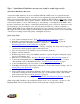
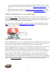
Locking Out the Centrifugal Advance 1. Remove the advance components including the springs, weights, and the advance stop bushing from the advance assembly. 2. Remove the roll-pin from the drive gear and remove the gear from the shaft. 3. Slide the shaft two inches out of the housing. 4. Rotate the shaft 180° and insert the advance stop bushing pin into the small hole on the advance plate (see illustration below). 5. Install the locknut and washer to the advance stop bushing pin.
Type 2 - Modified distributor (to serve as the cam sync) to be used with a crank trigger setup The cam sync drive provides a signal (every 360o of cam rotation) that allows for cylinder “fuelphasing” (controlling the point, BTDC, when the fuel is injected into the cylinder) and individual cylinder “timing control”. The cam sync signal, references the start of an injection or ignition firing sequence, and needs to occur 10o - 20o before the crank signal.
• • value in the Crank Trigger window (in the Operating Configuration table), up or down, until the “Dash” value and the crank value are the same. See Setting_The_Crank_Reference on page 25. Dynamically check the rotor phase. See Dynamically_Checking_Rotor_Phasing on page 30. Lastly, you will want to verify cam synchronization. See Verifying_Synchronization on page 11.
Removing Reluctors Use a permanent black marker and clearly identify (mark) the reluctor that is lined up or in-phase with the sensor pole piece. Remove the distributor and remove the reluctors that were not marked, making sure that the reluctor that was identified/marked is not removed! The residual metal, that was once a reluctor tab, needs to be completely removed from the reluctor ring to avoid false triggering.
• • • • • • Install the distributor then “bump” the starter until it engages the oil pump drive while applying a light downward pressure. Once the oil pump drive is engaged, rotate the engine back to the timing mark on the dampener that will represent the maximum timing the engine will see at full power. Turn the base of the distributor so that the distributor cap terminal for cylinder number 1 is aligned with the rotor in this position. Tighten the distributor down.
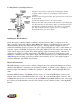
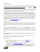
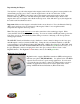
MSD Cam Sync Drive Shown below is MSD’s cam sync distributor, part number 2340. Inductive pick-up (sensor) Installing the Cam Sync Distributor The cam sync (signal) needs to occur 10o – 20o before the “Crank Reference” angle (see Setting_The_Crank_Reference on page 25 ). For example, if the “Crank Reference” angle is set to 45o BTDC (number 1 cylinder, compression stroke), the cam Magnet sync should be installed between 55o and 65o‘s BTDC.
Repositioning the Magnet You may have to reposition the magnet in the magnet carrier, if the rotor phase is unacceptable for the desired timing at peak power. Next, rotate the engine back to the 10 - 20o before the “Crank Reference” (55 – 65o BTDC). Once there, remove the magnet carrier and note the position of the Inductive Pick-Up (IPU) sensor and mark the magnet carrier where the IPU aligns. Remove the magnet carrier by loosening the center flush mount cap screw.
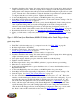
Type 5 - All-in-One, Crank and Cam Sync Distributor Currently MSD makes two all-in-one cam and crank (signal) distributors (see below). MSD all-in-one Ford distributor Part Number 2382 Crank Pickup MSD all-in-one Chevy distributor Part Number 2345 Camshaft pickup The All-In-One IPU distributor has both a cam and crank sensor built into a single unit. Quick Setup Guide • • • • • • • • • • • • Find TDC, cylinder number one (1), compression stroke. See Find_TDC on page 20.
The MSD All-In-One Distributor 2 wire connector (wires from the blue pole piece) must be changed to the 2 way black male Metripack connector (included in IPU kits). Crimp the seals and female terminals on with the correct crimping tool. Use Packard crimper, PN 12014254 or MSD’s Pro-Crimp Tool, PN 35051, with Weathertight Dies, PN 3509.
Type 6 - Using GM’s Oil Pump/Cam Sync Drive (P/N 1104068) Used in Conjunction with BigStuff3’s 24 tooth Wheel. For standalone Coil-on-Plug (COP) systems. Quick Setup Guide 1. Find TDC, cylinder number one (1), compression stroke. See Find_TDC on page 20. 2. Install the GM cam sync drive at TDC, then “bump” the starter until it engages the oil pump drive while applying a light downward pressure. Make sure it is fully seated and tighten it down. 3.
The table below shows the position the BigStuff3 Cam wires need to occupy in the new connector housing (positions A, B & C). The new connector housing has the A, B & C terminal locations molded into the housing. GM Cam Synch Drive Pin A Pin B Pin C BS3 LS1 CAM Connector Pink/black stripe wire Brown/white stripe wire Red wire Pin Function Ground Signal +12V The Delphi tool, required to remove the terminal pins from the BigStuff3 Cam housing, is also shown below.
Next, install the terminal pins into the new connector housing per the table above. Lastly, snap the secondary lock back onto the back of the new connector housing. Plug the connector into the cam sync drive. The terminal locations (A, B, & C) molded into the new connector housing are in the same order (based on the connector tab) as is shown below for the Cam Sync drive.
Find GM Cam Sync Falling Edge To find the Cam Falling Edge a voltmeter and a jumper wire are required.. A crankshaft degree wheel is also recommended. The following outlines the process. • Roll the crankshaft back 30o Before Top Dead Center (BTDC). A crankshaft degree wheel or balancer timing tape will help expedite the process. If neither is available, the following formula can be used to measure the distance, on the surface of the balancer that equals 30o. Multiply the diameter of the balancer by 3.14.
Type 7 – MSD Mag44 (Magneto) Quick Setup Guide • • • • • • • • • • Find TDC, cylinder number one (1), compression stroke. See Find_TDC on page 20. Roll the engine back to 50o BTDC. Install the crank trigger. Line up the sensor with the magnet. See Crank_Trigger_Considerations on page 21. Roll the engine forward to the position BTDC (cylinder 1) equal to the max power timing. Phase the rotor and/or reluctor. Connect the red BigStuff3 wire to green crank trigger wire.
as the crank signal. To confirm this, type the letters B-A-L simultaneously see B_A_L on page 30. Make sure the PC is communicating with the GEN3 ECU. A small box will appear near the tool bar in the upper right corner of the BigComm software screen. If the synchronizer ball is gray and is rotating eccentrically within the box, the cam signal is occurring before the crank signal. If the ball turns red, a problem exists, since the cam signal is occurring at the same time as the crank signal.
• • • • • • • Rotate the crankshaft back to 30o BTDC position and the voltmeter attached to the E3 and J2 terminals, the voltmeter should read 12 Volts (the Switched 12-Volt wire on the main harness must be is connected and “live”). Very slowly, rotate the crankshaft clockwise towards TDC. As soon as the voltmeter reading drops to zero Volts (or very close to zero Volts) stop rotating the crankshaft.
• • The UEGOR reading in the “Dash” must read 28. See Dash_Window on page 29. o Note: There is a cam sync issue if the UEGOR reading is any number other than 28. The cam sensor will need to be moved until UEGOR reads 28. Lastly, use a timing light to verify that the BigStuff3 “Dash” timing advance value equals the timing value seen (with a timing light) at the crank.
other than this number, then there is a synchronization problem between the cam and crank. The cam sensor may need to be moved to correct the cam sync problem. “Specific Details” Measuring Distances on the Surface of a Dampener. The following formula can be used to measure the distance on the radial face of the balancer. In this example, 10o BTDC is being calculated. Accurately measure the diameter of the dampener, then multiply the diameter by 3.14.
Using the Degreed Dampener or a Dampener with Timing Tape on it, instead of a degree wheel Make sure that the pointer is solidly mounted so that it will not move and that you can see the numbers on the radial face of the dampener. TDC Procedure Very slowly and carefully (via a breaker bar on the crankshaft bolt) rotate the crankshaft until the piston lightly touches the piston stop. Write down the number the pointer is indicating on the degree wheel.
In order to avoid this problem BigStuff3 recommends using a system that has four magnets (for a V8) embedded in the trigger wheel. As the magnets pass by a stationary non-magnetic pickup a sine wave is created, which is used to trigger the ignition. The magnet-in-the-wheel design produces a more accurate trigger signal and will not create a false trigger, like magnetic pickups have to potential to do.
Rotor Phasing Rotor phasing is important for regular OE ignition systems, but it is vital for high energy ignition systems where the spark has to jump or arc from the rotor tip to the distributor cap terminal. MSD distributors are designed with the rotor “in-phase” or aligned with the reluctor to work with their ignition systems (e.g. 6A box).
For example, with the Crank Reference set to 50o BTDC, the rotor needs to be retarded by 30o (crankshaft degrees) to achieve good rotor phase for a desired advance of 20o. The table below outlines how this number was derived.
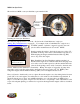
Start by removing the cam gear at the bottom of the distributor shaft by removing the roll pin with a 1/8” punch. Pull the distributor shaft out of the distributor housing. Remove the snap ring at just below the reluctor. Using a hammer and non-destructive punch, strike the reluctor circumferentially until it slides down the shaft, fully exposing the roll pin used to hold it in place. See the photos below. Roll pin slot in the distributor shaft.
“Crank Reference” window in the BigComm “Operating Parameter Configuration” Window. The “Crank Trigger” window to be used for all non-COP based systems For non-COP engines: If using a 4magnet (pole) crank wheel the value inputted into this cell must be 4. Static Test Timing Window Once the Distributor is installed and the engine is running, you must use a timing light to check the “Crank Reference” value entered into the BigComm software.
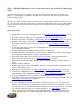
Cam/Crank Advance (CamCrkAdv). Will be available for COP applications in March 09. Add to the “Dash”, the variable called CamCrkAdv (see below). This variable displays in “real-time” (the engine is running) the relationship between the cam sync pulse and the first crank pulse. The reading is in degrees; adjust it to read between 10 – 20o when the engine is running. Below is a screen print from an oscilloscope showing the cam signal occurring 11o before the crank signal.
The cam signal occurs 11o before the crank signal The crank signal occurs 11o after the cam signal Setting the Crank Reference for Coil-0n-Plug Engines (not for distributor based engines) With COP systems the crank reference values will be from about 330 to 370. For example, since the crankshaft (balancer) was moved 10o after TDC (ATDC) subtract 10o from 360o (360o - 10o = 350o) and input 350o into the Crank Reference input box as shown below.
Use a timing light to confirm that the value inputted into the “Crank Reference” (in the COP window, not the Crank Trigger window) exactly matches the value at the crankshaft. The spark advance value displayed in the “Dash” window (see below) must match the value shown on the crank dampener. If they do not match, change the value (move the number up or down) in the “Crank Reference” window until the value in the “Dash” window matches the crank dampener value exactly.
Static Test Timing Window Dynamically Checking Rotor Phase Illustration shows rotor in-phase with cap terminal To check rotor phasing dynamically, the distributor cap will need to be modified so that the position of the rotor tip to the cap terminal can be observed when the engine is running. To do this, a large hole must be made in a distributor cap, near a terminal that can be easily observed. To help see the rotor tip, mark the top of it with white correction fluid.
With COP engines using HED cam and crank sensors, like the GM LSx engines, the synchronization status is provided immediately during cranking, so there is no need to rev the engine to 2000 rpm. If the synchronizer ball is gray and is rotating eccentrically within the box, the cam signal is occurring before the crank signal. However, if the ball turns red, a problem exists, since the cam signal is occurring at the same time as the crank signal.
How to Connect the BS3 Two (2) Wire Magnetic Sensor to the BS3 LS1 Main Wire Harness The LS1 main wire harness was designed to interface with the stock, three wire Hall Effect Device (HED) sensor. BigStuff3’s 24 tooth wheel and sensor kit uses a two (2) magnetic sensor. The steps, necessary to modify the LS1 main wire harness to accept the two wire sensor, are outlined below.
GEN3 ECU - Ignition Settings for GM Cam Sync Drive When using the GM Cam Sync drive and a BigStuff3 24 tooth wheel, the Factory or Dealer Ignition Configuration, must be as follows: • • • • • • • • Ignition Type: COP Ignition Drive: Inductive: FYI - when COP is selected for Ignition Type, the Ignition Drive is also automatically selected.