
User guide


Rev 1.0
21
Important Notes Summary:
• Rotor phase must be checked when using large retard values in the Driveshaft Error Table.
• The Timer Enable sequence will be reactivated, every time the throttle is closed and then opened
again (if you get off and then on the throttle again during a pass). Until the “Blend” feature is active.
• The three “Boost Spark Retard Tables “are not functional with the SR
2
system.
• Make sure all of the magnets in the magnetic ring are all installed in the SAME direction.
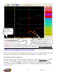
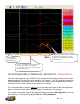
• If the TOSS_rpm trace is erratic switch the wires!
• To ensure that the 1
st
Gear Retard system becomes active when the trans-brake or clutch are released,
make sure the Minimum RPM & TPS values are exceeded while on the 2/3-Step when the trans-
brake is on or the clutch is depressed.
• The SR
2
1
st
Gear Retard system allows only one Timer Enable activation. To eliminate the
potential of activating the Timer Enable wire during the pre-stage burnout, put the Timer enable wire
on its own On/Off switch. After the burnout, turn on the switch.
• The timer enable wire must have 12V applied to it the moment the trans-brake button or clutch is
released. See relay wiring diagrams earlier in this manual.
• The SR
2
system requires that the timer enable and DAE trigger wires be on separate On/Off switches.
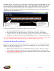
• Make sure the “Minimum RPM” in the Boost Parameters section is set 500 RPM below your 2 Step
RPM Hi (3-Step) RPM setting under Configuration/Operating Configuration from the main
BigComm toolbar
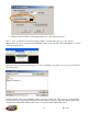
Next, immediately save the calibration (the file
ending in .big) from the GEN3 ECU into the
new SR2_BigComm folder!!