BigStuff3 - GEN3 1st Gear Spark Retard with Spark Retard Traction Control System (SR2) Rev 1.
System Description 1st Gear Spark Retard with Spark Retard Traction Control System (SR2) - SR2 uses two independent timing retard systems to control driveshaft speed. Both systems are triggered and function simultaneously when 12V is applied to the Timer Enable wire (12V redirected from the trans-brake or clutch). The first gear timing retard system also has “Time-out” and “Blend” features. The “Time-out” feature helps to eliminate “sticking” the tire.
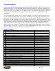
What the System Includes and its Capabilities • • The (SR2) wire harness – This harness allows a driveshaft speed sensor to be incorporated into the system. Embedded control software to control ignition timing retard, including user defined control and configuration tables. The functionality of these tables will be explained later in this manual. The SR2 system also includes the “Extended Replay” data acquisition option, which can log data from eighteen (18) seconds to approximately five (5) minutes.
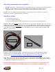
maximum and a .125 Watt min (to 2 Watt max) resistor is needed. A resistor is not required with the MSD Super 8 ignition system. Installation of the relay will be addressed later in this manual. How to Install the SR2 System The SR2 Harness Installation 3-Step Enable wire.
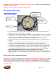
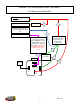
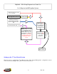
BigStuff3 – SR2 Wiring Diagram Using a Trans-Brake 2 & 3-Step via the MSD Ignition Switched 12V Source in the Vehicle Data Trigger Wire, Hdr. 2, Y2 On/Off Switch Starting Line Timing (or optional Starting Line VE or optional 3-Step) wire, Hdr. 2, W1 Timer Enable Wire, Hdr1, L2 ON/OFF Switch - The SR2 1st Gear Retard Control System requires an in-line On/Off switch to turn the “Timer Enable” signal wire On and Off.
BigStuff3 – SR2 Wiring Diagram for a Clutch Car 2 & 3-Step via the MSD Ignition System Switched 12V Source in the Vehicle Data Trigger Wire, Hdr. 2, Y2 On/Off Switch Starting Line Timing (or optional Starting Line VE or optional 3-Step) wire, Hdr. 2, W1 Timer Enable Wire, Hdr. 1, L2 ON/OFF Switch - The SR2 1st Gear Retard Control System requires an in-line On/Off switch to turn the “Timer Enable” signal wire On and Off.
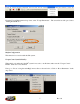
From the Torque Management drop down, select “Torque Parameters”. The screen below will open. Select “Timing Retard Mode”. Misfire Configuration This function is not active with the SR2 system. Torque Control (enable/disable) When this box is unchecked, the SR2 system is not active. At this time, make sure the “Torque Control Enable” check box is not checked. Next, go to “Boost” along the main BigComm toolbar, as shown below. Click on “Boost Parameters” in the drop down. 7 Rev 1.
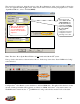
The screen below will open. Only the sections of the “Boost Parameters” table, enclosed with a yellow ring below, are applicable with the SR2 system. Each section will be discussed in the paragraphs below. Under “Spark Retard Mode”, select “1st Gear (RPM)”.
The RPM value in this cell should be 500 RPM below the Max 2-Step RPM value in the Op Cfg tab Next, go back to the main tool bar and select “1st Stage Boost Retard”. The screen below will open. The amount of timing retard applied, by the GEN3 ECU at each RPM point, is determined using the “1st Stage Boost Spark Table” shown below.
Use the mouse to drag the green line to the desired Retard and/or RPM value. The new Retard and RPM value will be displayed and the table below the graph will be updated with the new values once the mouse button is released, as shown below.
When the mouse is released the graph will automatically rescale itself and the values in the table will be automatically updated as well, as shown below. 11 Rev 1.
Next, configure the 1st Gear Timer Override and Blend Rate cells. The length of time that the 1st Gear Retard system remains active is defined by the user in the cell titled “1st Gear Timer OverRide” shown below. Once the 1st Gear Retard system times-out (from the point when the trans-brake or clutch are released), the system transitions to a zero retard value (back to the timing in the spark map) using the blend feature. The blend rate is defined by the user in the cell titled “BlendRate” shown below.
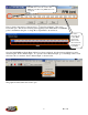
1st Gear Retard Period from Timer Enable “ON” point. Hit “Z” to zero out the cursor Blend time period and the slope of the line are defined by the number of “Counts” inputted into the “Blend Rate” cell under Boost Parameters Shows 1st Gear Retard system is functional per time period defined in calibration (1.1.seconds). After 1.
The GEN3 “Replay” data acquisition system will graph of the amount of timing retard used during any given pass. The timing retard variable displayed in the replay is called “TorqRetard”. The GEN3 ECU uses the timing retard values in the Driveshaft Error Table below to apply timing retard as a function of driveshaft error.
• With the system disabled, use the Replay function to collect data from a pass. Once a “good” pass has been recorded using the “Replay” internal data logger, go to the “Torque Management” drop down screen from the main BigComm tool bar and select “Driveshaft Replay” as shown in the screen print below. The following screen will open allowing you to choose the Replay you want to use to set up your “Desired Driveshaft Curve”. Double left click on the preferred Replay and the screen below will open.
Traction Control Specific Signals shown in the right margin of the Driveshaft Replay window 1. DS Error = Driveshaft Error – Shows the difference between the TOSS_rpm and the TISS_rpm. Values will be displayed in positive and negative numbers. Negative numbers indicated that the previously defined curve (the TISS curve) exceeded the Des TOSS curve. 2. TOSS_rpm = Driveshaft Speed – Shows the actual driveshaft speed recorded. 3.
1. Gear1_Rtd – The amount of timing retard applied at that RPM point, within the “1st Gear Timer Override” period The “Desired Driveshaft Table” represents an eight second (8) time period, broken up into 80 cells each representing 1/10 of a second. In each of the eighty (80) cells, the user can define the desired driveshaft speed. All the usual editing features are employed (Fill, Interpolate, etc…) in the table as well, but only a row at a time.
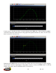
Interpreting SR2 Replay Graphs Timer enable comes ON Shows the timing retard being applied during the pass to control the driveshaft speed to the desired curve 1st Gear Timing Retard System. Shows period until blend feature starts Traction control system, based on timing retard. This system can intervene at any time once the “Timer Enable” wire is activated. It will intervene, if needed, even while the 1st Gear Retard system is active.
Blend time period and the slope of the line are defined by the number of “Counts” inputted into the “Blend Rate” cell under Boost Parameters 1st Gear Retard Period from Timer Enable ON point Shows 1st Gear Retard system is functional per time period defined in calibration (1.1.seconds). After 1.
Next, save, and then unzip the new SR2_BigComm zip file into the new SR2_BigComm folder. The new software is available at http://208.109.66.74/BigComm_Setup.exe. There is an underscore_ character between BigComm and Setup.exe. Lastly, (and most importantly) connect your PC to the GEN3 ECU and immediately save the calibration from the BS3 GEN3 ECU into the new SR2_BigComm folder! This calibration must be used as your baseline moving forward.
Next, immediately save the calibration (the file ending in .big) from the GEN3 ECU into the new SR2_BigComm folder!! Important Notes Summary: • • • • • • • • • • Rotor phase must be checked when using large retard values in the Driveshaft Error Table. The Timer Enable sequence will be reactivated, every time the throttle is closed and then opened again (if you get off and then on the throttle again during a pass). Until the “Blend” feature is active.