Operator Manual, Supercharger 60 R3.0 TABLE OF CONTENTS 1. INTRODUCTION AND SYSTEM DESCRIPTION .................................................................. 5 2. CONDENSED OPERATING INSTRUCTIONS ....................................................................... 8 2.1 Constant Current Charge (normal mode) ............................................................................................... 8 2.2 Constant Voltage........................................................................
Operator Manual, Supercharger 60 R3.0 4.20 DS5A - FULL: .......................................................................................................................................... 21 4.21 DS5B - DISCH: ........................................................................................................................................ 21 4.22 DS6A - CAP FAIL: ..................................................................................................................................
Operator Manual, Supercharger 60 R3.0 8.8 DISCHARGE VOLTAGE CUT-OFF.................................................................................................... 38 8.9 FULL DISCHARGE. .............................................................................................................................. 39 8.10 CURRENT TRACKING. ........................................................................................................................ 39 8.11 VOLTAGE CONTROL. ................
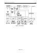
Operator Manual, Supercharger 60 R3.0 TABLE OF FIGURES Figure 1 - Block Diagram ...................................................................................................................................... 7 Figure 2 - Front Panel .......................................................................................................................................... 20 Figure 3 - Line Voltage Wiring, 115V ...........................................................................................
Operator Manual, Supercharger 60 1. R3.0 INTRODUCTION AND SYSTEM DESCRIPTION Congratulations! You now own the finest battery Charger-Analyzer available today. The Supercharger is a precision instrument designed to charge and analyze NICKEL-CADMIUM, LEAD-ACID and other rechargeable batteries exactly as recommended by the battery manufacturers.
Operator Manual, Supercharger 60 R3.0 The TIMER provides all the required timing functions related to the charge and discharge durations. Digital time and speed selectors provide the external inputs, while the four digit readout of the CLOCK provides the elapsed time display. The CURRENT CONTROL interprets the programmed current values and controls the angle of firing of two SCR's to maintain a constant current in accordance to the feedback received from a precision shunt.
Operator Manual, Supercharger 60 R3.
Operator Manual, Supercharger 60 2. R3.0 CONDENSED OPERATING INSTRUCTIONS CAUTION: Disconnect power and batteries before performing any internal maintenance. Failure to observe this caution may result in serious damage to the unit and injury to the operator. NOTE 1: Depress the RESET button before turning the power on, or before connecting or disconnecting the battery. NOTE 2: The current selector potentiometers display three digits indicating XX.X AMPS. e.g.: in order to select 4A dial 040 (04.
Operator Manual, Supercharger 60 2.2 R3.0 Constant Voltage 2.2.1. Battery Voltage 2.2.1.1. Enter the nominal battery voltage using the cell selector (see chart on page 19). 2.2.1.2. Program the charge (maximum) current in the Topping Current selector. 2.2.1.3. Program sufficient time in the Total Time selector to allow the battery to reach the required charge under constant voltage charge (consult battery manufacturers specifications).
Operator Manual, Supercharger 60 2.3 R3.0 Peak Voltage Charge 2.3.1. Nominal Battery Voltage 2.3.1.1. Enter the nominal battery voltage using the cell selector (see chart on page xxx). 2.3.1.2. Select transfer from Main to Topping on Peak or stop on Peak. 2.3.1.3. Program the Main and Topping Charge currents as required. 2.3.1.4. Program the Main and Total Time selectors to allow the battery to reach the required charge level (consult battery manufacturers specifications).
Operator Manual, Supercharger 60 2.4 R3.0 Discharge NOTE 1: Do not place batteries on the Temp-Plate during discharge. Due to the normal heating of the battery a false Overtemp may be generated later during the charge process. NOTE 2: Do not attempt to discharge with the voltage mode selector in the Float or Peak voltage modes. Voltage and current faults will occur depending on the battery voltage and the cell selector setting. 2.4.1. 2.4.2. Number of Cells 2.4.1.1. Enter the number of cells. 2.4.1.
Operator Manual, Supercharger 60 3. R3.0 SPECIFICATIONS 3.1 CHARGE 3.1.1. CONTROL: SCR, air cooled. 3.1.2. MAXIMUM CURRENT: 50 AMPS. 3.1.3. MINIMUM INCREMENT: 0.1 AMP. 3.1.4. ACCURACY and STABILITY of settings: ±1% of reading, ±0.1 AMP. 3.1.4.1. FLOAT: • The reference voltage is set at the equivalent of 2.33V/cell (LeadAcid). • The Cell Selector provides the basic reference as nominal battery voltage, e.g.: a 24V battery is entered as 24 on the Cell Selector. • Current reduction from within 0.
Operator Manual, Supercharger 60 3.1.5. 3.1.6. 3.1.7. 3.1.8. 3.1.9. R3.0 MODES: 3.1.5.1. Main and topping for Constant Current 3.1.5.2. Constant Voltage 3.1.5.3. Peak Voltage. TIMER: 3.1.6.1. 1 to 9 hours for MAIN charge time and 1 to 60 hours for TOTAL time. 3.1.6.2. Time can also be programmed in minutes by selecting the FAST mode in the TIMER SPEED selector switch (Front Panel). 3.1.6.3.
Operator Manual, Supercharger 60 R3.0 3.1.12.1. 3 AMPS idling plus ½ the value of the charging current; e.g. when charging 40 AMPS the line current is 23 AMPS (Note: nominal values, line voltage and frequency dependent). 3.2 DISCHARGE 3.2.1. CONTROL: Transistors, air cooled. 3.2.2. MAXIMUM CURRENT: 3.2.3. 3.2.2.1. 60 AMPS. Total power dissipation must not exceed 1.2KW (1200 watts, the product of battery voltage and battery current). 3.2.2.2.
Operator Manual, Supercharger 60 3.2.6. 3.2.7. 3.2.8. 3.2.9. R3.0 TERMINAL VOLTAGE: 3.2.6.1. Programmable, in accordance with the number of cells selected, at the equivalent of 1 VOLT/cell. 3.2.6.2. TOLERANCE: ±1% ±0.1 VOLT. 3.2.6.3. NOTE 1: Due to cable/connector losses the voltage registered by the Charger-Analyzer will be lower than the actual battery voltage (up to 0.2V depending on current). 3.2.6.4. NOTE 2: Terminal voltage is ignored in the full discharge mode. OVERHEAT PROTECTION: 3.2.
Operator Manual, Supercharger 60 3.3.2.4. 3.3.3. 3.3.5. 3.4 NOTE: The colon flashes at the rate of one cycle per second regardless of the selected mode. ACCURACY AND STABILITY: 3.3.3.1. 3.3.4. R3.0 ±0.01% POWER FAILURE PROTECTION: 3.3.4.1. An internal rechargeable battery maintains (for several hours) the clock and other vital circuits for a dependable resumption of operation after a power failure. 3.3.4.2. The colon will be lit in case of a power failure. 3.3.4.3.
Operator Manual, Supercharger 60 3.5 DIGITAL PANEL METERS 3.5.1. 3.5.2. 3.5.3. 3.6 R3.0 VOLTMETER: 3.5.1.1. Accuracy (system): ±0.25% of reading, ±0.1V in the 200V scale, ±0.01V in the 20V scale, ±0.005V in the 2V scale. 3.5.1.2. Input impedance: 1 M-OHM. 3.5.1.3. Scale 2V, 20V and 200V (1.999V, 19.9V and 199.9V) for external measurements and 20V and 200V for internal (battery) measurements. AMMETER: 3.5.2.1. Accuracy (system): ±0.5% of reading, ±0.1A 3.5.2.2. Scale: 200A (199.9A) SHUNT: 3.
Operator Manual, Supercharger 60 4. R3.0 CONTROLS AND DISPLAYS 4.1 4.2 4.3 M1 - Ammeter 4.1.1. 0 to 199.9ADC DIGITAL PANEL METER. 4.1.2. Positive sign indicates charge current. 4.1.3. Minus sign indicates discharge current. M1 - Voltmeter 4.2.1. 0 to 1.999VDC, 0 to 19.99VDC and 0 to 199.9VDC DIGITAL PANEL METER. 4.2.2. Indicates battery voltage in the internal (20/200V) position and voltage present at the RED (+) and BLK (-) jacks in the 2/20/200V external positions.
Operator Manual, Supercharger 60 4.8 4.9 R3.0 SW4 - CELL SELECTOR: 4.8.1. Two digit selector to program the battery terminal voltage as a function of the number of cells. 4.8.2. Rate: 1.75 volts per cell for charge and 1.0 volts per cell for discharge. 4.8.3. Used also in the Float and Peak Voltage modes to enter nominal battery voltage. SW5 - DIGITAL VOLTMETER INPUT SELECTOR: 4.9.1. External, 2/20/200V scale. 4.9.2. Internal, 20/200V scale. 4.10 SW6 - VOLTAGE MODE SELECTOR: 4.10.1.
Operator Manual, Supercharger 60 R3.
Operator Manual, Supercharger 60 R3.0 4.12 DS1A - RESET: 4.12.1. Indicates that the unit is in standby. 4.13 DS1B - CYC END: 4.13.1. Flashing (with pulsating beeper) cycle end. Indicates that the unit has completed its cycle. 4.14 DS2A - DUAL: 4.14.1. Indicates that the DUAL rate mode (MAIN and TOPPING) is selected. 4.15 DS2B - MAIN: 4.15.1. Indicates that the unit is in MAIN charge. 4.16 DS3A - SINGLE: 4.16.1. Indicates that the SINGLE rate mode (Topping) is selected. 4.17 DS3B - TOP: 4.17.1.
Operator Manual, Supercharger 60 R3.0 4.25 DS7B - OVR HEAT: 4.25.1. Indicates that the discharge bank is overheated. 4.26 DS8A - VOLT FLT: Indicates voltage fault. 4.26.1. Continuous: battery connected with polarity reversed. 4.26.2. Flashing: (during charge) battery voltage in excess of 1.75 volts per cell or in excess of 85 volts, or open circuit. 4.27 DS8B -CURR FLT: 4.27.1. Indicates that the actual current differs from the programmed value by more than 1A. 4.28 DS9 - CC 4.28.1.
Operator Manual, Supercharger 60 5. R3.0 MODES OF OPERATION 5.1 CONSTANT CURRENT CHARGE 5.1.1. DUAL RATE: 5.1.1.1. The battery is charged at the main rate for a preset time, at the end of which, the current is switched automatically to the topping rate for the remainder of the total time selected. 5.1.1.2. Charging is automatically terminated at the end of the total time selected (cycle end), or as a fault if: • Battery overtemperature is detected (Overtemp fault).
Operator Manual, Supercharger 60 5.2 R3.0 CONSTANT VOLTAGE CHARGE. 5.2.1. The battery is charged at the topping rate for a preset time. 5.2.2. When the battery voltage is within 0.5V of the selected float voltage, the charging current begins to diminish, and settles to the level of current required to maintain the battery at the selected float voltage. 5.2.3.
Operator Manual, Supercharger 60 5.3 R3.0 PEAK CHARGE. 5.3.1. Transfer from Main to Topping on Peak voltage. 5.3.1.1. The battery is charged at the main rate for a preset time. 5.3.1.2. When the battery voltage reaches the programmed peak voltage, the charging current transfers from main to topping. 5.3.1.3. Charging is automatically terminated at the end of the total time selected (cycle end), or as a fault if: • Battery overtemperature is detected (Overtemp fault).
Operator Manual, Supercharger 60 5.4 R3.0 DISCHARGE. NOTE: For battery voltages greater than 32V, the discharge current is automatically limited to 30A. A current fault condition will result if more than 30A is programmed. 5.4.1. ANALYSIS (AUTO CUT-OFF): 5.4.1.1. The battery is discharged at the selected rate for a preset time. 5.4.1.2.
Operator Manual, Supercharger 60 6. R3.0 OPERATING INSTRUCTIONS 6.1 GENERAL 6.1.1. Verify RESET 6.1.1.1. 6.1.2. 6.1.3. 6.1.4. Verify that the reset button is depressed before turning power on. Connect the Battery 6.1.2.1. Connect the battery cable to the batteries and the Temp-Plate. 6.1.2.2. If only one battery is used, connect the free plug to the shorted receptacle provided in the Temp-Plate. 6.1.2.3. Observe polarity when using the single cell adaptor. 6.1.2.4.
Operator Manual, Supercharger 60 6.2 R3.0 CONSTANT CURRENT CHARGE. 6.2.1. 6.2.2. Main Charge 6.2.1.1. Program Main charging rate and time duration. 6.2.1.2. Verify that the Timer Speed is consistent with the required elapsed time. Topping Charge 6.2.2.1. Program Topping charging rate and total time of charge (Total time = Main + Topping Times). 6.2.2.2. Start in Dual Rate 6.2.2.3. Depress the Two Rate (white) control button. 6.2.2.4.
Operator Manual, Supercharger 60 6.3.4. R3.0 RUN 6.3.4.1. Start the Charger-Analyzer in the Single Rate mode. The charger will start to reduce the charging current when the battery voltage is within 0.5V of the float level. 6.3.4.2. The charge will terminate automatically (CYCLE END) when the TOTAL TIME selected is reached. 6.3.4.3. The charge will terminate as a FAULT if the MONITOR CIRCUIT detects that: • Battery temperature exceeds 45oC/113oF (BATTERY OVERTEMP FAULT).
Operator Manual, Supercharger 60 6.5 R3.0 DISCHARGE NOTE: Do not discharge batteries on the Temp-Plate. Normal battery heating of the Temp-Plate during discharge will generate a false battery Overtemp fault when attempting to recharge it. 6.5.1. 6.5.2. Current and Time 6.5.1.1. Program the discharge rate and time duration. 6.5.1.2. Verify that the Timer Speed is consistent with the required elapsed time. RUN 6.5.2.1. Depress auto discharge (BLUE) control button, for analysis to one volt per cell.
Operator Manual, Supercharger 60 6.6 R3.0 Float/Peak Voltage Chart CHART RELATING THE COMPUTED FLOAT AND PEAK VOLTAGES TO THE SELECTED NOMINAL BATTERY VOLTAGE 6.6.1. The Cell Selector becomes a Nominal Battery Voltage selector in other than the Constant Current settings of the Voltage Mode Selector. 6.6.2. NOTE: Nominal battery voltage is referenced on the basis of 1.2V/cell for Nickel-Cadmium batteries and 2V/cell for Lead-Acid batteries. e.g.
Operator Manual, Supercharger 60 6.7 R3.0 OPERATING NOTES AND PRECAUTIONS 6.7.1. Make sure that the instrument is in the reset position before turning power on or off, or before connecting or disconnecting batteries. 6.7.2. When a cycle is terminated either automatically or by resetting, wait about two to three seconds before re-starting in any mode (the control switch circuit has a time delay that ignores switch selections during a 2 to 3 second interval). 6.7.3.
Operator Manual, Supercharger 60 7. R3.0 INSTALLATION 7.1 7.2 BENCH SPACE. 7.1.1. The Charger-Analyzer system occupies 19" x 17" (48.3 cm x 43.2 cm) of table top space for the charger and 10" x 25" (25 cm X 63.5 cm) for the Temp-Plate. 7.1.2. Allow also at least 6" (15.2 cm) of separation from the wall and adjacent equipment, in order to maintain proper air flow (VITAL!). 7.1.3.
Operator Manual, Supercharger 60 R3.
Operator Manual, Supercharger 60 8. R3.0 VERIFICATION OF PERFORMANCE The Charger-Analyzer has been designed, manufactured and tested to give thousands of hours of trouble free operation, but if you find that your unit is not performing properly (or as expected), please refer first to the operating instructions for re-assurance that proper procedures are being followed.
Operator Manual, Supercharger 60 8.3 R3.0 TIMER VERIFICATION. 8.3.1. Settings: 8.3.1.1. Set the Main and Topping Charge Current Selectors to zero. 8.3.1.2. Set both Time Selectors to zero. 8.3.1.3. Set the Timer Speed Switch to the test (center) position. 8.3.2. NOTE: Current and voltage readings must remain at zero during the following tests. If voltage starts to rise, which may lead to voltage a fault, verify that the current selectors are completely at zero. 8.3.3.
Operator Manual, Supercharger 60 8.4 BATTERY OVERTEMP CUT-OFF. 8.4.1. 8.4.2. 8.4.3. Settings: 8.4.1.1. Set current selectors to zero. 8.4.1.2. Set the timer speed switch in the normal position (to the right). 8.4.1.3. Set time selectors to 1/01 and cell selector to 20. 8.4.1.4. Connect the battery cable to the unit but make no battery or TempPlate connections. The red Overtemp light will be on. Temp-Plate simulations resistors: 8.4.2.1. Connect one 16.
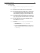
Operator Manual, Supercharger 60 8.6 8.7 8.8 R3.0 REVERSE POLARITY TEST. 8.6.1. Connect the battery cable to a voltage source (CAL-100 or low current power supply and reverse the polarity). Start at zero and advance towards -0.5V 8.6.2. The unit will show a fault through the alarm and the voltage fault light at about 0.25V (-0.20V to -0.35V). 8.6.3. Alternatively, connect the battery cable, with the single cell adaptor, to one cell with the polarity reversed or to a standard 1.
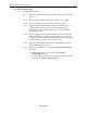
Operator Manual, Supercharger 60 8.9 R3.0 FULL DISCHARGE. 8.9.1. Settings: 8.9.1.1. Set the Current selectors to zero. 8.9.1.2. Set the Time selectors to 1/01. 8.9.1.3. Set the Cell selector to 20. 8.9.2. Start the unit in the full discharge mode (red). Unit will run. Increase the discharge current selector to any value above 1 AMP (010). Unit will continue to run. 8.9.3. Switch to Auto discharge. Unit will go to Capacity Failure. Disconnect from the voltage source. Reset. 8.
Operator Manual, Supercharger 60 R3.0 8.12 FLOAT VOLTAGE: 8.12.1. Settings: 8.12.1.1. Set the Voltage Control Selector to Float 8.12.1.2. Set the Current Selectors to zero. 8.12.2. Connect the Battery Cable to the battery and note the battery voltage. 8.12.3. Using the chart in figure 3 (page 19) find in the FLOAT column the closest higher voltage (by at least 1V) to the observed voltage on the battery. Set the cell selector to the value indicated in the Cell Selector column. 8.12.4.
Operator Manual, Supercharger 60 R3.0 8.14 METERS 8.14.1. Verify the battery voltage and charge/discharge current readings by comparing against a CAL-100 Calibrator or a reference voltmeter and a reference ammeter (or reference shunt). 8.14.2. See 8.1 for adjustments.
Operator Manual, Supercharger 60 9. R3.0 CALIBRATION • NOTE 1: The Charger-Analyzer must be verified (and calibrated if required) at least once every 12 months, or earlier if deviation from performance is observed. (see first note on section 7). • NOTE 2: Perform adjustments only when changing parts and components that require recalibration. • NOTE 3: Perform a Verification of Performance prior to attempting a calibration (see Section 7, page 25).
Operator Manual, Supercharger 60 R3.0 • NOTE 3: Insert an external shunt/ammeter in series with any of the battery leads (Use the Single Cell adaptor to facilitate the connection or simply use the CAL-100 which is a calibrator designed specifically to test and certify Charger-Analyzer Battery Charger-Analyzers. • NOTE 4: The charge output current wave is in the form of short pulses (at twice the line frequency). The use of clamp-on meters and moving magnet meters will yield erroneous readings.
Operator Manual, Supercharger 60 R3.
Operator Manual, Supercharger 60 R3.0 Figure 7 - Control Switch Board Adjustments 9.2.3. CONTROL SWITCH (see fig 8). NOTE: For voltage measurements use pin 14 on the Current Control Board as reference common. 9.2.3.1. R10 - AMPLIFIER ZERO. • Static test (no battery or Calibrator). • Adjust a reading of 0.000V " 0.003V at E3 on the CONTROL circuit board. • NOTE 2: Newer versions of this circuit board no longer have a zero adjustment.
Operator Manual, Supercharger 60 R3.0 • Set the Cell Selector at 20, connect a voltage source set to approximately 21V and start the Charger-Analyzer in AUTO Discharge • Adjust for a Discharge CUT-OFF (Capacity Failure) at 20.0 volts. • NOTE: This step requires that the Overvoltage cut-off on the MONITOR circuit board be previously calibrated. 9.2.3.3. CLOCK-TIMER • No adjustments on this board.
Operator Manual, Supercharger 60 R3.0 • NOTE 1: Other currents can also be used for High Current calibration (20A minimum). • NOTE 2: Adjustments of R28 and R25 are interactive. Therefore, It will be necessary to repeat the adjustments once or twice to achieve exact results. • The Voltage reading at E3 (shunt amplifier output) must correspond to the current as follows: voltage at E3 = -0.1V/A ±2%. • Examples: 40 A equals -4.00V ±0.08V 20 A equals -2.00V ±0.04V 10 A equals -1.00V ±0.02V 5 A equals -0.
Operator Manual, Supercharger 60 R3.0 Figure 9 - Monitor Board Adjustments 9.2.4. MONITOR (see fig 12) NOTE: Use pin 14 on the card connector (or the Test Point E0 on the Control Board) as ground reference for voltage measurements. 9.2.4.1. U12 pin 1 - BATTERY VOLTAGE • This point corresponds to one tenth of the battery voltage present at the input terminals. 9.2.4.2. U12 pin 7 - CELL SELECTOR • This point corresponds to one tenth volt per cell, e.g. 2.00V = 20 cells.
Operator Manual, Supercharger 60 9.2.4.3. R3.0 R62 – OVERVOLTAGE • (no battery) • Set the Current Selectors to zero and set the Cell Selector to 20 (1.75V/cell) • Connect an external voltage source (Power Supply or CAL-100) to simulate the battery voltage, set at approximately 34V. • Start the Charger-Analyzer in either of the Charge modes and adjust this trimpot for an Overvoltage charge cut-off at 35.0V ±0.1V. 9.2.5.
Operator Manual, Supercharger 60 R3.0 Figure 10 - Voltage Control Board Adjustments 9.2.5.2. VOLTAGE CONTROL - See [Figure 10] 9.2.5.2.1. R11, FLOAT VOLTAGE: • Connect a CAL-100 Calibrator or a power supply capable of producing at least 10V (very little current required) to the CAL (-) and CAL (COMMON) test points. The positive lead to COMMON and the negative lead to CAL (-). • Set the calibrator/power supply to 2.70V to simulate a battery that has 27.0V.
Operator Manual, Supercharger 60 R3.0 • Adjust R11 as required to reduce the charging current to zero at a simulated battery voltage of 28.0V • Note: This test can also be performed directly on a battery (no calibrator required), preferably one that is “soft” (rapid voltage change). Adjust R11 as necessary to maintain the battery at the required voltage (see Verification of Performance, section 7, page 27). 9.2.5.2.2. R14, PEAK VOLTAGE:.
Operator Manual, Supercharger 60 R3.
Operator Manual, Supercharger 60 R3.0 10. TROUBLESHOOTING AND REPAIRS 10.1 TROUBLESHOOTING The following are hints and directions to help you locate the most probable causes of deviation of performance as established in the procedures of section 8. 10.1.1. UNIT CHARGES ON MAIN BUT DOES NOT CHARGE ON TOPPING AND DOES NOT DISCHARGE. Defective Topping/Discharge current selector or defective Control board. 10.1.2. UNIT CHARGES PROPERLY ONE BATTERY BUT CANNOT CHARGE TWO BATTERIES AT HIGH RATES.
Operator Manual, Supercharger 60 R3.0 Do not connect a battery under this condition! 10.1.12.9.1.12 CURRENT TRACKING IS OFF BY A SMALL CONSTANT AMOUNT. Amplifier zero or low current calibrate out of adjustment (CONTROL board). 10.1.13.9.1.13 CURRENT TRACKING IS OFF BY A SMALL AMOUNT WHICH INCREASES AS THE PROGRAMMED VALUE IS INCREASED. High current calibrate out of adjustment (CONTROL board). 10.1.14.9.1.15 THE UNIT STARTS BUT EXHIBITS A CURRENT FAULT AFTER SOME TIME (from a few seconds to a few minutes).
Operator Manual, Supercharger 60 R3.0 10.2 FINDING A SHORTED DISCHARGE TRANSISTOR Since all discharge transistors are wired in parallel, a single shorted transistor will short the entire bank. The procedure that follows will allow the finding of the shorted transistor without requiring removal and testing of each device individually. 10.2.1. EQUIPMENT REQUIRED • Digital Voltmeter. • Battery, 24V. • Lamp, 24V (lamp must draw at least 0.5 A). 10.2.2. PROCEDURE 10.2.2.1.
Operator Manual, Supercharger 60 R3.
Operator Manual, Supercharger 60 R3.
Operator Manual, Supercharger 60 R3.
Operator Manual, Supercharger 60 R3.0 11. REPLACEABLE MODULES AND PARTS 11.1 CIRCUIT BOARDS 9879101001 - METERS (LED) 9879903004 - VOLTAGE CONTROL 9879960001 – CONTROL SWITCH 9879903009 – CLOCK (older units) 9879903010 – TIMER (older units) 9879903109 – CLOCK-TIMER (newer units) 9879903011 – CURRENT CONTROL 9879960012 – MONITOR 9879903013 – POWER 11.
Operator Manual, Supercharger 60 R3.0 12. BATTERY TESTING NOTES Note, hazardous condition: Handle batteries with extreme care as they are capable of very high discharge rates if short circuited. Check the Battery Manual, IMM or Aircraft Manufacturer Instructions for information on charging, discharging and testing.
Operator Manual, Supercharger 60 R3.0 13. DISCLAIMER • The Supercharger is a precision system intended to be operated by personnel qualified in the servicing of aircraft batteries. • The end user must establish suitability in the intended application. • JFM Engineering’s responsibility is limited to the repair/replacement of any malfunctioning part of the system (not responsible for any losses incurred from the usage of the system).
Operator Manual, Supercharger 60 R3.0 14. REVISION INDEX Table 2 - Index of Revisions REVISION 1.0 2.0 2.1 DATE 21 January 2001 15 January 2003 23 July 2003 3.0 4 October 2007 NOTES Release New Clock-Timer Board and additional Peak function Overvoltage is now set at 1.75V/cell (was 1.70). Numerous other text updates (clarifications).