Model 4555 User’s Manual Publication #: 107679-001 Rev. A July 2005 Another quality product from: 7128 Shady Oak Road, Eden Prairie, MN 55344 Phone: (952) 949-9009 Fax: (952) 949-9559 E-mail: info@researchinc.com www.researchinc.
Dear Valued Customer: Thank you for purchasing a Model 4555 PanelIR® Infrared Pyropanel. We believe it is the finest system of its type and are confident you will think so too. For technical assistance, training, replacement parts and assemblies, or any other problems or questions, contract our Field Service specialists. They will do everything they can to help you or will put you in touch with someone who can.
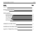
Model 4555 PanelIRTM User Manual Section Contents Page SAFETY 1 PRODUCT DESCRIPTION 2 7 Dimensions INSTALLATION Mechanical Installation Electrical Installation Single Phase Wiring Three Phase Wiring Lamp Installation Thermostat Wiring Pressure Switch Wiring Blower Wiring 11 12 14 15 19 20 20 21 OPERATING INSTRUCTIONS 22 MAINTENANCE INSTRUCTIONS 23 Appendix A Multiple Heater Wiring 24
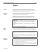
Model 4555 PanelIRTM User Manual Safety Safety General Electrical Safety The Model 4555 Heater is designed for safe operation. Nevertheless, installation, maintenance, and operation of the heater can be dangerous for a careless operator or maintenance person. For your safety and the safety of others, read the instructions in this manual and follow these warnings to help prevent accident or injury.
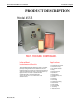
Model 4555 PanelIRTM User Manual Product Description PRODUCT DESCRIPTION Model 4555 FAST. FOCUSED. CONTROLLED. Infrared Heat. Instantaneous Results. Applications The Model 4555 High Density Infrared Panel heater is a modular, panel-type heating unit that combines radiant and convection heating techniques. A forced air flow system turns waste heat into usable energy and allows the heater to operate efficiently at very high power levels.
Model 4555 PanelIRTM User Manual Product Description Product Description-PanelIR 4555 Heater Construction Metal Housing The Model 4555 PanelIR uses rugged stainless steel and aluminum housing to contain the lamps, blowers and reflector. Reflector A polished aluminum or ceramic reflector is installed in the housing in back of the lamps to direct the heat toward the product. The choice of ceramic or polished aluminum is based on the application.
Model 4555 PanelIRTM User Manual Product Description Product Description-PanelIR 4555 cont. Heater Construction cont. Infrared Lamps Short Wavelength Lamp These lamps are generally used in applications where a product is to be heated or cured. These lamps may be operated in horizontal or vertical orientations.
Model 4555 PanelIRTM User Manual Product Description Product Description-PanelIR 4555 cont. Controls The model 4555 PanelIR heater is designed to be powered by one of the standard Research Inc. control panels. The model of the control panel required depends on (1) the voltage and amperage required to power the panel, (2) the electrical service in the facility, and (3) the type of temperature control required for the process.
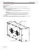
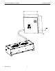
Model 4555 PanelIRTM User Manual Product Description B A C Research, Inc.
Model 4555 PanelIRTM User Manual Product Description Product Description-PanelIR 4555 Control Panel Voltage Circuit Breaker Single Phase Dimensions A B C Model 900-240-20 240 Volt 20 amp 20 inch 16 inch 8.62 inch Model 900-240-40 240 Volt 40 amp 20 inch 16 inch 8.62 inch Model 900-240-60 240 Volt 60 amp 20 inch 16 inch 8.62 inch Model 925-240-30 224 Volt 30 amp 20 inch 20 inch 8.62 inch Model 925-240-60 240 Volt 60 amp 24 inch 24 inch 12.
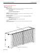
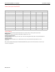
Model 4555 PanelIRTM User Manual Product Description SPECIFICATIONS – PanelIR 4555 MODEL Lighted Length(in/mm) Dimension A Dimension B Dimension C Dimension D Model 4555-05-06 5 (127) 8.58 5.38 6.00 9.41 Model 4555-05-12 5 (127) 8.58 10.75 12.00 9.41 Model 4555-10-06 10 (254) 13.58 5.38 6.00 14.41 Model 4555-10-09 10 (254) 13.58 7.75 9.00 14.41 Model 4555-10-12 10 (254) 13.58 10.75 12.00 14.41 Model 4555-16-06 16 (406) 19.58 5.38 6.00 20.
Model 4555 PanelIRTM User Manual Product Description How to Order – PanelIR Model 4555 1.
Model 4555 PanelIRTM User Manual Product Description Accessories & Replacement Parts – PanelIR 4555 ACCESSORIES AND REPLACEMENT PARTS PanelIR 4555 Model Description Set of two edge reflectors for: ER-4555/4-05 5 inch (127 mm) length ER-4555/4-10 10 inches (254 mm) length ER-4555/4-16 16 inches (406 mm) length ER-4555/4-25 25 inches (635 mm) length ER-4555/4-38 38 inches (965 mm) length Short Wavelength Lamps 103390-001 5 inch, 500 watt 103390-003 10 inch, 1600 watt 103390-005 16 inch, 100
Model 4555 PanelIRTM User Manual Installation Installation Tools Required: • Phillips Screwdriver • Slotted Screwdriver • Hammer • Metal Punch • Pliers • Tape Measure • Tin snips/Metal cutting scissors. MECHANICAL INSTALLATION As shown in Figure 3-1, four ¼-20 screws are provided on the top of the Model 4555 heater for mounting purposes. The heater can be attached directly to a suitable frame structure or mounting brackets using these four screws.
Model 4555 PanelIRTM User Manual ELECTRICAL INSTALLATION Installation CAUTION! All internal wiring of the model 4555 Panel IR should be high temperature insulated wire as specified below or of an equivalent type: • Lead wire type PFAH or TFE, 600V Maximum, 250°C maximum, UL listed. • Ampacity based on National Electrical Code Table 310. As shown in Figure 3-2, the Model 4555 contains two electrical terminal blocks, one each mounted on the internal heater housing, under each heater end cover.
Model 4555 PanelIRTM User Manual Installation Heater Figure 3-3 Single Zone Wiring Incoming Power Bus Bar Terminal Blocks WARNING! The electrical power required to operate the 4555 is extremely dangerous. Make sure all electrical power that is to be provided to the Model 4555 is adequately turned off prior to making any electrical connection to the heater. NOTE: The following instructions are for single-phase electrical wiring of the Model 4555. See next section for three-phase wiring.
Model 4555 PanelIRTM User Manual Installation Single Phase Wiring Prepare heater unit for wiring Remove electrical connection “knock-outs” Install high temperature wire Wiring Power to Heater Research, Inc. 1. Remove the three screws from each of the end covers on each end of the heater using the Phillips screwdriver. 2. Carefully remove each of the end covers and set them aside so that they are not damaged. 1.
Model 4555 PanelIRTM User Manual Installation Three Phase Wiring Prepare heater unit for wiring Remove electrical connection “knock-outs” Install high temperature wire 1. Remove the three screws from each of the end covers on each end of the heater using the Phillips screwdriver. 2. Carefully remove each of the end covers and set them aside so that they are not damaged. 3. Remove the Bus Bars from the terminal blocks. Leave the jumper bars in place. 1.
Model 4555 PanelIRTM User Manual Installation Figure 3-5 Single Zone 3 Phase Wiring Diagram Research, Inc.
Model 4555 PanelIRTM User Manual Installation Multi-Zone Wiring The Model 4555 can also be wired so that multiple heating zones are produced within the heater. When configured for multi-zone operation, each zone of lamps is electrically controlled by its own power control device. Wiring the Model 4555 for multi-zone operation is as follows: Prepare heater unit for wiring 1. Remove the three screws from each of the end covers on each end of the heater using the Phillips screwdriver. 2.
Model 4555 PanelIRTM User Manual Figure 3-6 Installation Multi-Zone Bus Bar Preparation BUS BAR PLASTIC SPACER REMOVE THIS AREA TO CREATE 2 6-LAMP BUS BARS JUMPER BAR Install high temperature wire Wiring Power to Heater Research, Inc. 1. On each end, use the tape measure to measure the distance from the center of each terminal strip ‘zone’ to the point at which the supply power and the high temperature wire are to be joined. 2.
Model 4555 PanelIRTM User Manual Installation Lamp Installation CAUTION! Wear soft, clean, oil free flannel or plastic gloves when handling halogen, quartz lamps. Oils and contaminates are readily transmitted to the quartz by unprotected hands and can cause premature lamp failure. Lamp Mounting 1. Insert the lamp lead wires through the reflector and snap the lamp into the spring clips provided (Figure 3-7). If the lamp clips are excessively tight, gently spread the clip wider.
Model 4555 PanelIRTM User Manual Wiring Thermostat Installation A thermostat is mounted to the backside of the Model 4555 air plenum inside the heater body (Figure 3-8). The thermostat is a feature of the model 4555 that safeguards the heater from overheating. The thermostat is rated for 120 volt 15 amp service.
Model 4555 PanelIRTM User Manual Forced Air Blower Wiring Installation The Model 4555 has an integral blower to provide cooling air to the lamps and reflectors. The blowers operate on 230 VAC 50/60 Hz. The blowers are wired to terminal blocks 5-6 (Figures 3-9,10). All applicable electrical standards and codes must be followed when wiring the forced air blowers. Figure 3-10 Blower, Thermostat and Pressure Switch Wiring Diagram Research, Inc.
Model 4555 PanelIRTM User Manual Operating Instructions Operating Instructions Operation of the Model 4555 is relatively straightforward once installed and properly (electrically) wired to an appropriate power control source. In addition, the forced-air blower system, pressure switch and heater thermostat must be connected to an appropriate power supply in order to operate.
Model 4555 PanelIRTM User Manual Maintenance Instructions Maintenance Periodic inspection for dirt and contaminates on the heater, blower mechanism, and lamps, and removal of such, will ensure that the Model 4555 continues to operate efficiently and will extend lamp life. In dirty environments or heating operations the lamps may become contaminated by, dust, fingerprints or other foreign matter.
Model 4555 PanelIRTM User Manual Appendix A Appendix A Multiple Heater Wiring DETERMINING THE CURRENT PER LAMP 1. Calculate the percentage of the applied voltage to the lamp’s rated voltage: Percent Voltage = 2. Applied Voltage X 100 Rated Voltage of Lamp Use Figure A-1 to determine the percent of power dissipated by the lamps at that percent voltage. Or for greater accuracy, calculate the percent of power dissipated: Percent of Power Dissipated = (Percent Voltage)1.54 3.
Model 4555 PanelIRTM User Manual Appendix A Figure A-1 Voltage and Temperature Single Phase Loads The line current for single-phase loads can be calculated using one of the following methods: 1. Determine the current per lamp. If the applied voltage to the lamps is different, calculated the lamp current as explained on page 21. 2. Determine the number of lamps. 3. Calculate the line current: Line Current = Lamp Current X Number of Lamps.
Model 4555 PanelIRTM User Manual Appendix A Figure A-2 Single-Phase or DC Input Wiring Diagram 480 V SINGLE PHASE ↔ ↓ ← MODEL 4555-25-12 (12) 2599T3 LAMPS 30,000 WATTS @480 MODEL 4555-25-12 (12) 2599T3 LAMPS 30,000 WATTS @480 VOLTS Research, Inc.
Model 4555 PanelIRTM User Manual Appendix A Three Phase Balanced Loads A three-phase load is one where the load for all three phases dissipates the same power. In the case of the Model 4555, there should be an equal number of the same wattage lamps connected to each phase. The line current for three phase loads can be calculated using one of the following methods: 1. Determine the power dissipated per lamp. 2. Determine the number of lamps. 3. Calculate the total power dissipated in the load. 4.
Model 4555 PanelIRTM User Manual Appendix A Figure A-3 Balanced Three-Phase Load Wiring Diagram 480 VOLT 3 PHASE ↔ ↓ ← MODEL 4555-25-12 (12) 2599T3 LAMPS 30,000 WATTS @480 VOLTS MODEL 4555-25-12 (12) 2599T3 LAMPS 30,000 WATTS @480 VOLTS MODEL 4555-25-12 (12) 2599T3 LAMPS 30,000 WATTS @480 VOLTS Research, Inc.
Model 4555 PanelIRTM User Manual Three-Phase Unbalanced Loads Appendix A Often it is not possible to connect the lamps in the Model 4555 to make a balanced load. In this case, the three line currents supplying the heater lamps can be calculated as follows: 1. Determine the number of lamps in each load. 2. Determine the current per lamp. 3. Calculate the load current for each of the three loads based on the number of lamps in each load and the current per lamp.
Model 4555 PanelIRTM User Manual Appendix A Figure A-4 Unbalanced Three-Phase Load Wiring Diagram 480 VOLT 3 PHASE ↔ ↓ ← MODEL 4555-25-12 (12) 2599T3 LAMPS 30,000 WATTS @480 VOLTS MODEL 4555-25-12 (12) 2599T3 LAMPS 30,000 WATTS @480 VOLTS MODEL 4555-25-06 (6) 2599T3 LAMPS 15,000 WATTS @480 VOLTS Research, Inc.