Model 5420 User’s Manual Publication #: 107399-001 Rev. 1 May 2005 Another quality product from: 7128 Shady Oak Road, Eden Prairie, MN 55344 Phone: (952) 949-9009 Fax: (952) 949-9559 E-mail: info@researchinc.com www.researchinc.
Dear Valued Customer: Thank you for purchasing a Model 5420 ControlIR® power controller. We believe it is the finest power controller of its type and are confident you will think so also. This instruction manual has been carefully prepared to ensure you will be able to easily install and operate the Model 5420 power controller and to fully realize all its inherent capabilities. We invite your comments as well as any issues you may have regarding this manual or the Model 5420.
Model 5420 ControlIRTM User Manual Section Contents Page SAFETY 1 DESCRIPTION 2 3 Dimensions INSTALLATION Load Wiring Connections Control Wiring Connections 5420mA 4 5 OPERATING INSTRUCTIONS Model 5420 Model 5420E Timer Settings Model 5420mA MAINTENANCE AND TROUBLE SHOOTING Schematics Model 5420 Schematics Model 5420E Schematics Model 5420mA 6 7 8 9 10 11 12 13 SPARE PARTS LIST Model 5420 Model 5420E Model 5420mA Exploded Parts View 14 15 16 17
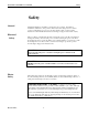
Model 5420 ControlIRTM User Manual Safety Safety General Electrical Safety The Model 5420 Power Controller is designed for safe operation. Nevertheless, installation, maintenance, and operation of the heater can be dangerous for a careless operator or maintenance person. For your safety and the safety of others, read the instructions in this manual and follow these warnings to help prevent accident or injury.
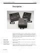
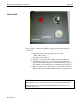
Model 5420 ControlIRTM User Manual Description Description Model 5420mA Model 5420E Model 5420E Model 5420 The Model 5420 ControlIR is a 15 amp power controller designed to control the voltage supplied to one of the many Research Inc. single lamp infrared heaters. It is available for 120, 240 and 480 volt control with an 8 foot power cord. Control features are either: a manually set potentiometer, a manually set potentiometer with timer, or a 4-20mA external control signal.
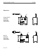
Model 5420 ControlIRTM User Manual Description Dimensions 120 and 240 VAC Model 5420 Model 5420E Model 5420mA 7.06 120 AND 240 VAC 5420 8.13 4.72 480 VAC Model 5420 Model 5420E Model 5420mA 7.06 480 VAC 5420 10.06 Research, Inc. 3 4.
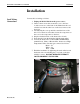
Model 5420 ControlIRTM User Manual Installation Installation Load Wiring Connections Research, Inc. Connect the load wiring as follows: 1. Unplug the Model 5420 from the power source. 2. Remove the 4 screws that secure the cover to the base. 2 of the screws are on the back of the 5420 where the cord exits the base and the other 2 are on the bottom next to the front feet. 3. Carefully lift the cover up and tilt toward the front of the unit.
Model 5420 ControlIRTM User Manual Model 5420mA Control Wiring Installation To connect the wires for the 4-20mA input on the Model 5420mA unit follow these steps: 1.) Remove the 90° connector from the top of the 5420mA. 2.) Remove the (1) larger screw to take the connector apart. 3.) Install wires through the rubber strain relief on the top half of the connector. Loosen the 2 screws of the cable clamp and slide the cable through. 4.) Strip the wires and solder into pins 1 and 3. Pin 1 is + pin 3 is -.
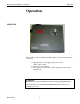
Model 5420 ControlIRTM User Manual Operation Operation Model 5420 The operation of the basic Model 5420 is simple once the heater has been connected. 1.) Plug the unit in to the appropriate power source. (120V, 240V, 480V) 2.) Turn the power switch on. 3.) Set the power level from 0 to 100% using the potentiometer (black knob). WARNING! Infrared heaters can get extremely hot; do not leave them operating unattended.
Model 5420 ControlIRTM User Manual Operation Model 5420E The operation of the Model 5420E is simple once the heater has been connected. 1.) Plug the unit in to the appropriate power source. (120V, 240V, 480V) 2.) Turn the power switch on. 3.) Set the power level from 0 to 100% using the black knob. 4.) Set the heater “ON” time on the timer by turning the clear plastic dial with the red pointer. See Timer Settings section of the manual for more information on the timers range settings. 5.
Model 5420 ControlIRTM User Manual Operation Model 5420E Timer Settings The timer has 6 different range settings: 0-5 seconds, 0-50 seconds 0-5 minutes, 0-50 minutes, 0-5 hours, and 0-50 hours. The primary range is displayed below the green push button as: sec, min, or hrs. The secondary range is displayed as a decimal point between the 1-5 numbers and the zero that follows. Example 1.
Model 5420 ControlIRTM User Manual Operation Model 5420mA The Model 5420mA requires an external 4-20mA signal to operate. This unit will work with PLC’s and other programmable controllers to start and stop the heating cycle as well as regulate the output voltage during the cycle. 1.) Plug the unit in to the appropriate power source. (120V, 240V, 480V) 2.) Turn the power switch on. 3.) Set the power level by supplying a 4-20mA signal from an external source.
Model 5420 ControlIRTM User Manual Maintenance Maintenance and Trouble Shooting Maintenance No routine maintenance is required. The 5420 should be kept clean and dry. If cleaning is required, unplug unit before cleaning. Troubleshooting Troubleshooting should be done by Qualified Personnel especially if the 5420 needs to be opened up. SYMPTON ACTION Heater will not turn on. - unit is plugged into an energized receptacle - on/off switch is in the ‘On’ position.
Model 5420 ControlIRTM User Manual Maintenance Schematics Model 5420 120/240 VAC 480 VAC Research, Inc.
Model 5420 ControlIRTM User Manual Maintenance Schematics Model 5420E 120/240 VAC 480 VAC Research, Inc.
Model 5420 ControlIRTM User Manual Maintenance Schematics Model 5420mA 120/240 VAC 480 VAC Research, Inc.
Model 5420 ControlIRTM User Manual Spare Parts Spare Parts Model 5420 Model 5420-120 Replacement Parts Item Description Part Number 1 150 k Ohm Potentiometer 067156-003 2 Solid State Relay Kit 107593-001 3 Two Position Rocker Switch 106820-003 4 Knob with White Pointer 055770-001 5 Terminal Strip 107353-001 6 Line Cord and Plug 086822-001 Model 5420-240 Replacement Parts Item Description Part Number 1 1 Meg Ohm Potentiometer 067156-001 2 Solid State Relay Kit 107593-002 3 Two Position Rocker Switch 106
Model 5420 ControlIRTM User Manual Spare Parts Spare Parts Model 5420E Model 5420E-120 Replacement Parts Item Description Part Number 1 150 k Ohm Potentiometer 067156-003 2 Solid State Relay Kit 107593-001 3 Two Position Rocker Switch 106820-003 4 Knob with White Pointer 055770-001 5 Terminal Strip 107353-001 6 Line Cord and Plug 086822-001 7 Interval Timer with Push Button 107407-001 Model 5420E-240 Replacement Parts Item Description Part Number 1 150 k Ohm Potentiometer 067156-001 2 Solid State Relay
Model 5420 ControlIRTM User Manual Spare Parts Spare Parts Model 5420mA Model 5420ma-120 Replacement Parts Item Description Part Number 1 150 k Ohm Potentiometer 067156-003 2 Solid State Relay Kit 107593-004 3 Two Position Rocker Switch 106820-003 4 Knob with White Pointer 055770-001 5 Terminal Strip 107353-001 6 Line Cord and Plug 086822-001 10 4-20 mA Receptacle 083618-002 Item 1 2 3 4 5 6 10 Model 5420ma-240 Replacement Parts Description Part Number 1 Meg Ohm Potentiometer 067156-001 Solid State Re
Model 5420 ControlIRTM User Manual Spare Parts 6 10 3 4 1 7 5 2 Model 5420 120 VAC and 240 VAC 10 4 8 1 3 7 9 6 5 2 Model 5420 480 VAC Research, Inc.