
User's Manual

Cod.Doc.2550041-REV02.doc
Pagina 44
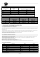
5.4 - Advanced menu parameters
Setup Description Range Default
Group 1 Panel nominal data
P1.01 Nominal frequence 50Hz= 0 60Hz=1 0
.02 Current Trasformer ratio (CT 100/5 = 20) 1…2000 20
.03 System (220V monophase, 220V triphase, 380V triphase) 0=220M 1=220T 2=380T 0
Group 2 Engine start-up
P2.01 500 rpm signal from alternator or gen. (started engine) 0= from alternator Vac
1= permanent magnet alt. (saprisa)
2= pre-excited alternator (D+)
0
.02 Started engine alternator batterycharger voltage threshold 3-30V 10
.03 Started engine generator voltage threshold 20-500V 50
.04 Starting with power failure On=1 Off=0 1
.05 Preheating time 1-60 sec 7
.06 Number of starting attempts 1-10 6
.07 Duration of starting attempts 1-30sec 5
.08 Pause time within starting attempts 1-20sec 10
.09 Automatic test enabling with remote stop signal presence 0= start not enable
1= start enable
1
.10 Alarm enabling delay at starting (oil/V/freq.) 1-60sec 8
.11 Air time 0-240 sec 5
.12 Air switch-off threshold 30-255V 100
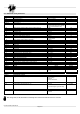
Group 3 Motor stop
P3.01 Stop times (electromagnet closing time / gasoline engine stop time) 1-30sec 10
.02 Decelerated funct. time 1-60 sec 30
.03 Cooling time 1 – 300sec 120
Group 4 Protections
P4.01 Minimum frequency (fixed delay 5sec) 80 – 100 % 90%
.02 Maximum frequency (overspeed) 100 – 120% 110%
.03 Maximum frequency al. tripping delay 0-15 sec 2 sec
.04 Battery minimum frequency 7-12V 9
.05 Battery maximum frequency 13 – 17V 17V
.06 Load maximum current 10 – 2550A 100A
.07 Maximum current delay 0 – 600sec 10
.08 Tripping delay of “500rpm failure” (strap breaking) 0 –10 sec 5
.09 “Mechanical failure” tripping delay 0 - 10 sec 5
Group 5 Various Range Default
P5.01 Generator and network contactor closing delay 0,1 –5 sec 1
P5.02 Remote start input function 0= normal 1= ejp/t 0
P5.03 Re-commutation lock on network in case of alarm during EJP/T 1 = on
0 = off
0
P5.04 Hourcounter value 0 – 999.999 0
Group 6 Programmable outputs
P6.01 Programmable relay (terminal 63)
0= choke / air
1= glow plugs
2= alarm
3= fuel electrovalve
1= glow plugs
P6.02 Programmable relay (terminal 53 - 54)
0= alarm
1= decelerator
2= electromagnet or gasoline stop
0= alarm
P6.03 Programmable relay (terminal 62)
0= siren
1= alarm
0= siren
Note : Range P7.01, P7.02, P8.01 E P8.02 must always set in reference to 230V also if P1.03 =1 or P1.03=2