
User's Manual

Cod.Doc.2550041-REV02.doc
Pagina 43
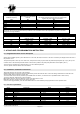
Cable connection and fixing power on contactor’s terminals and output terminals, must be in accordance to following data
Contactor (check the type
installed in the panel)
Minimum and maximum section
of the cables connected without
terminals
Minimum and maximum terminals fixing power .Warning!!! During
the power cables connection, don’t move the auxiliary wires from
the contactor terminals and check if they are properly fixed
togheter with power cables in the terminals.
Tipo mm Nm Ibft
BF9T 1-6 1,5-1,8 1,1-1,5
BF12T 1-6 1,5-1,8 1,1-1,5
BF18T 1-6 1,5-1,8 1,1-1,5
BF26T 2,5-6 2,5-3 1,8-2,2
BF38T 2,5-16 2,5-3 1,8-2,2
CL04 2,5-16 1,4 1,02
WARNING !! If the installation of the product is not in accordance to the specifics descripted above, can cause problems in terms of
functionality and can also compromises warranty conditions. Then Tecnoelettra srl won’t be responsible for any direct or not direct
damage due to wrong installation.
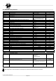
POWER CONVERSION TABLE
Contactor Ith
thermal current
Panel maximum power
400Vac 3P+N
kVA max / I max
Panel maximum power
230Vac 3P+N
kVA max / I max
Panel maximum power
230Vac 1P+N
kVA max / I max
25A 17kVA / 25A 10kVA / 25A 9kVA / 40A
32A 22kVA / 32A 12kVA / 32A 11kVA / 50A
45A 31kVA / 45A 18kVA / 45A 16kVA / 72A
56A 38kVA / 56A 22kVA / 56A 20kVA / 89,5A
60A 42kVA / 60A 24kVA / 60A 22kVA / 96A
5 - AT206 PANEL PROGRAMMATION INSTRUCTION
5.1 - Programmation menu access description
With the board in RESET position, press TEST button for 5 seconds; after that, the entrance in the menu is showed by the display with the first code of
the parameter “U.01”.
This procedure permit to enter only in the “User menu”; that permits to modify only the normal use parameters (descripted in par. 5.3); by this you are
not able to enter in the technical parameters that can cause function problem in the panel (these parameters are descripted in par.5.4).
To have access to complete menu (advanced menu), you need a different password.
To have it, please contact the dealer or the manufacturer.
5.2 - Parameters modification instructions
TEST button permits to see the value of the parameter
START button permits to increase the value and STOP button permit to decrease the value. For the time setting, START button increase the hours
value and STOP button increase the minutes value.
To save the value set and exit from parameter, press RESET then AUT button. (In advanced menu only RESET button to save and exit)
To exit from parameter without saving, press AUT button.
MEAS button permits to change (increase) the number of the parameter in a menu
MAN button permits to change (increase) the number of the menu
At the end of the programmation, press AUT than RESET buttons to return definitively from programmation mode to operative mode.
5.3 - User menu parameters
Setup Description Range Default
Group 1 Test
U.01 Automatic test interval time 1 – 30days 3 days
U.02 Test duration 1 – 30 min 10 min
U.03 Test start time 00:00 – 23:59 10:00
U.04 Test with load 0=with load 1=without load 1
Group2 Various
U.08 Siren relay closing time 0 – 60 sec 20 sec
U.09 Engine starting delay from EJP/T signal 0 – 99 min 25 min
U.10 Switching delay for EJP/T(1 wire) 0 – 30 min 5 min
Group3 Clock setting
U.11 Time 00:00 – 23:59 11:11