
r Manual
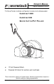

POWERWINCH CAPSTAN POWERED LIFT ASSIST
5
WIRING THE UNIT
WARNINGS
ALWAYS disconnect the battery before working on electrical equipment.
ALWAYS use the recommended wire size and rated circuit breakers. Failure
to use the furnished and recommended sizes can cause a fire hazard and
void warranty.
When routing the wiring, avoid sources of heat.
When routing the wiring, avoid sharp edges that can cut or fray the wire
insulation.
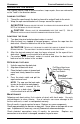
1. Locate a suitable location for the switch.
Location should be easily accessible when handling the rope from the
capstan.
Locate the switch outside the normal traffic patterns. This is to avoid
the switch being accidently stepped on or tripped over.
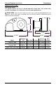
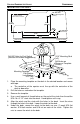
2. Drill a 5/8" hole through the mounting surface.
3. If attached, unscrew the rubber cap from the top of
the switch and install the switch from the underside of
the deck.
4. Fully thread the cap back onto the switch. Tighten the
jam nut from below deck to secure the switch.
5. Connect the two (2) red wires to the switch.
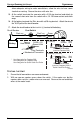
6. At the winch, terminate the wires from the winch with 5/16" ring terminals.
7. Route one BLACK wire from the winch to the battery location. Be sure to
allow adequate wiring to make connections, allow the wire to have some
slack when routing. Secure the wires with wire ties.
Tip: Before making the mechanical connection, slide a 2 1/2" piece of the
shrink tubing over one wire. Make the connection then slide the wrap over
the connection. Lightly heat the wrap until it shrinks around the terminals.
8. At the winch, terminate the BLACK wire with a 5/16" ring terminal. Attach the
new wire to the motor B
LACK wire with a 1/4 -20 screw and nut and shrink wrap.
9. At the battery, terminate the BLACK wire with a 3/8" ring terminal. Attach the
new wire to the
NEGATIVE (-) terminal of the battery.
10. Route one RED wire from the winch to the switch location. Be sure to allow
adequate wiring to make connections, allow the wire to have some slack
when routing. Secure the wires with wire ties.
11. Terminate each end of the R
ED wire with 5/16" ring terminals.
12. Connect the motor GREEN wire to the RED wire with a 1/4 -20 screw and nut and
shrink wrap.
13. At the switch position, connect the R
ED wire to one of the short wires from switch
with a 1/4 -20 screw and nut and shrink wrap.
Switch
Jam Nut
Switch Cap
5/8" Hole
pwcs006