
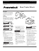
User Manual


Installation
MOUNTING
The winch can be mounted on the trailer
in the same position and location as an
existing hand winch. After removing the
hand winch, bolt the Powerwinch unit
using a minimum of (2) 3/8" Grade 5
machine bolts and lock nuts. The
Powerwinch Quick Mount Kit
(P7700000AJ) is available from the
dealer.
The cable hook on the winch and the bow
eye on the boat should be at the same
height when the boat is in the fully loaded
position on the trailer. If the bow eye is
too high, extra pull is required of the winch
and extra stress is exerted on the boat's
stern and bow eye.
To achieve equal height of the winch and
boat, raise or lower the winch stand. In
most cases, the trailer manufacturer will
have an adapter available for use with a
winch.
A minimum of 12
inch clearance is
required between the winch and the bow
eye to prevent the cable hook from being
drawn into the winch drum when the boat
is in the fully loaded position on the trailer.
If necessary, extend the bow stop to
obtain the clearance.
When using a double line pull (using a
3
Operating Instructions
pulley block), install an appropriate eye
bolt on the winch stand as close as
possible to the base of the winch. If a
Quick Mount Kit is used, make sure the
winch is in the forward position before
installing the eye bolt.
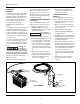
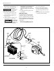
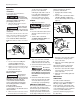
PERMANENT WIRING FOR MODELS
712A AND 912
To permanently wire the winch, refer to
Figure 1 follow the outlined procedures.
1. Attach the circuit breaker to the
positive (+) battery post or to the
positive (+) battery side of the starter
solenoid (See Figure 1).
Never attach the
circuit breaker to the
battery ground terminal.
2. Run the wire under the vehicle to the
battery, attaching at suitable intervals
to the vehicle frame. Use nylon wire
ties (not supplied) to secure the wire
to the vehicle frame about every 18
inches. If no wire ties are available
use electrician's tape. Avoid sharp
edges or places where the wire might
rub.
3. Attach the ground wire (black) to the
vehicle frame using a 5/16" bolt and
lock nut. Before attaching the wire,
clean the metal with a wire brush,
steel wool, or sandpaper.
4. Remove the knock out plug in the
spare tire well and draw the excess
wire up into the vehicle.
PERMANENT WIRING FOR
MODEL 315
To permanently wire the winch, refer to
Figure 2 follow the outlined procedures.
1. Strip approximately 3/8” of insulation
from each wire end.
2. Grasp one end of the red and black
wires, insert the wires into rubber boot
and the plug cover.
3. Attach the red wire to the gold
terminal and attach the black wire to
the silver terminal.
4. Firmly tighten the two screws that hold
the wires in place. Screw the plug cover
into the plug base and slide the rubber
boot firmly over the plug.
5. Run the red and black wires under or
through the vehicle. Drill holes to feed
the wires and be sure to protect the
wires from damage by using grommets
(not supplied). Worn wire insulation
can cause short circuits. At 10”
intervals, join the red and black wires
together using electrical tape or wire
ties.
6. Attach the 5/16” ring terminal to the
end of the black wire and crimp
together.
Battery
Terminal
*
5/16" Bolt
*
5/16"Lock Washer
And Nut
*
12 Volt Car
Or Truck Battery
Vehicle
Frame
*
NOT SUPPLIED
Figure 1 - Permanent Wiring Hookup for Models 712A and 912