LinkNet UniSer v Unit (USU) RF - FIBER Interface Modules User Manual Installation, Operation And Maintenance KAVAL WIRELESS TECHNOLOGIES 60 Gough Road Markham, Ontario, L3R8X7 Telephone: (888) 86-KAVAL Web: www.kaval.com E-mail: info@kaval.com Document #DCM000000104, Rev.
USU USER MANUAL DCM000000104 PROPRIETARY STATEMENT © 2000 KAVAL WIRELESS TECHNOLOGIES All rights reserved. No part of this publication, or any software included with it may be reproduced, stored in a retrieval system, or transmitted in any form or by any means, including photocopying, electronic, mechanical, recording or otherwise, without the prior written permission of the copyright holder.
USU USER MANUAL DCM000000104 TA B L E O F CONTENTS 1. USU MODULES........................................ 4 OVERVIEW ............................................................. 4 Theory Of Operation......................................... 4 Typical Application............................................ 4 MODELS................................................................. 5 BLOCK DIAGRAMS .................................................. 6 LNKFIB-H03 and LNKFIB-H04 Head-End Modules ............
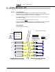
USU 1. USER MANUAL USU MODULES Overview Theory Of Operation The USU RF to Fiber Modules provide a single-band link from a Head-End Distribution center to multiple local antennae. RF Signals are distributed over a pair of Single-Mode Fiber-Optic Distribution Lines to each USU Remote. Each Head-End Module can interface to multiple Remote Modules, the number depending upon the Head-End Model. The Head-End Modules do not transmit directly out into the air.
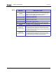
USU Models USER MANUAL MODEL DCM000000104 DESCRIPTION Wall, Shelf, or Rack Mounted Remote Module that connects to the Single-Mode Fiber-Optic Distribution Lines and provides a single US800TP duplex Antenna RF Distribution connection. This model covers USU Remote Module 800MHz Trunking / iDEN / Public-Safety Services (806-824 MHz / 851-869 MHz).
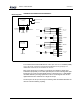
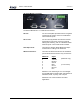
USU Block Diagrams USER MANUAL DCM000000104 LNKFIB-H03 and LNKFIB-H04 Head-End Modules Green Power On LED Micro-Controller Circuitry Red Fault LED CAN Interface To Head-End RS232 Interface To PC RF O u t "A" Ph o to d etecto rs & PreAmp s SM F .O . In (PIN Diodes) W ith UpLink G ain Control Fault Relay RF In p u t "A" L aser Dio d e SM F .O . O u t (Lasers) PreAmp Power Supply 120 / 240 VAC RF O u t "A" Ph o to d etecto rs & PreAmp s SM F .O .
USU USER MANUAL DCM000000104 US Remote Modules The US series Remote Modules have a Fiber-Optic transceiver pairs downlink and uplink filtering, and an downlink RF Power Amplifier. Printed: 03.05.
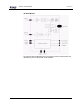
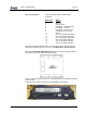
USU Connections USER MANUAL DCM000000104 LNKFIB-H03 and LNKFIB-H04 Head-End Module Connections The LNKFIB-H03 Head-End has two Downlink RF Inputs providing the signal for eight Downlink Optical Outputs arranged as groups of four, "A" and "B". It also has eight Uplink Optical Inputs combined in two groups of four providing RF Outputs "A" and "B". The RF and optical connections are all on the rear panel.
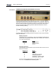
USU USER MANUAL DCM000000104 US Remote Module Connections The Remote Module has 1 or 2 SMA RF Connections.. RF Xcvr: For the normal (non -2) models there is a single RF Transceiver port used to connect to a distributed indoor antenna system. RF Tx & Rx: For the 2-Port (-2) models there are RF Transmit and Receive Ports used to connect to external filtering and combining, then to a distributed indoor antenna system. Consult with Kaval for details.
USU USER MANUAL User I/O Connection: DCM000000104 This is a standard 15-pin Female D-Sub Connector... DB15 Pin # 1 9 8 2 3 5 6 7 10 11 12 13 14 15 Signal CAN High CAN Low CAN Common Fault Relay - Closed for Fault Fault Relay - Common Fault Relay - Open for Fault +28 VDC at up to 0.5 Amp Ground Aux. In #1 (contact to ground) Aux. In #2 (contact to ground) Aux. In #3 (contact to ground) Aux. Out #1 (open collector) Aux. Out #2 (open collector) Aux.
USU USER MANUAL DCM000000104 Head-End to Remote Interconnects The Single-Mode Fiber-Optic interconnections between the Head-End and Remote Modules are to be made in whatever manner suits the system configuration. For the CAN Network connections please refer to DCM000000103. Fiber-Optic Connections All Fiber-Optic Cabling must use 9/125 or similar Single-Mode (yellow jacketed) high-quality cable. This cable should typically have less than 0.5 dBo (optical dB) insertion loss per kilometer.
USU Module Specifications USER MANUAL DCM000000104 Frequency Bands Maximum Downlink Power Maximum Uplink Power Combined at any Head-End RF Output. Includes the 4-way combiner loss.
USU Remote Module PerCarrier De-Rating USER MANUAL DCM000000104 All signals that fall within a given Pass-Band range will “share” power amongst them. A multiple channel effect is Intermodulation - signals produced from non-linear effects between the intended channel signals. This intermodulation may cause interference to receiving equipment. In order to minimize Intermodulation signals, Power de-rating must be applied.
USU Operation USER MANUAL DCM000000104 Normal Operation For both USU Head-End and Remote Modules ... POWER / OPERATING - This LED will be GREEN when the Module is operating. LASER - This LED will light GREEN when any one of the Lasers are operating. F.O. Input - (Remote only) This LED will light GREEN when an Optical Signal is received. FAULT - If the internal diagnostics detect a problem, then this LED will light Red. Fault Indications Each Module continuously performs internal diagnostics.
USU USER MANUAL DCM000000104 Configuration and PC Commands It is possible to re-configure Modules in the field, either with a Personal Computer (PC) or via the optional LinkNet Gateway Module. To use a PC it is necessary to connect the DB9 RS-232 connector on the Module to a standard DB9 RS232 Connector on the PC. On the PC a terminal emulation program such as HyperTerminal is used to communicate to the LinkNet Module. The settings are 9600 baud, 8 bits, no parity, and 1 stop bit.
USU Gain Adjustments USER MANUAL DCM000000104 Gain Adjustment is necessary to compensate for the variations in the Fiber-Optic components of the Head-End and Remote Modules. This must be done after Modules are deployed in a System, and anytime a Module is replaced. The adjustments are on an individual RF Path basis, and each path is adjustable downwards in 1dB steps up to -15dB. It is recommended that these adjustments be performed with the aid of a Signal Generator and Spectrum Analyzer.
USU Product Warranty RMA Procedure USER MANUAL DCM000000104 Please contact Kaval Wireless Technologies for a copy of the Standard Product Warranty. All returns, including warranty returns, must have a valid Return Material Authorization (RMA) number. Customers must contact KAVAL WIRELESS TECHNOLOGIES before shipping any product for warranty service and obtain a Returned Materials Authorization and detailed shipping instructions.
USU Laser Safety USER MANUAL DCM000000104 • CAUTION – use of controls or adjustments, or performance of procedures other than those specified herein may result in hazardous radiation exposure. Printed: 03.05.21,10:40 • This laser product is certified as a CLASS I laser product to the requirements of the US Federal Product Performance Standard for Laser Products contained in the regulations in 21 CFR Subchapter J. Class I laser products are not considered to be hazardous.
USU Antenna Installation USER MANUAL • • • DCM000000104 All Antenna Installation to be performed by Qualified Technical Personnel only. Antenna Installation Instructions and locations below are for the purpose of satisfying FCC RF Exposure Compliance requirements. The In-Building Antenna connection is via a coaxial cable distribution system with Signal Taps at various points connected to the fixed-mounted Indoor Antennae. This is shown in the figure in the Introduction.