In-Hancer Plus Bi-Directional Amplifier User Manual Installation, Operation And Maintenance KAVAL WIRELESS TECHNOLOGIES 60 Gough Road Markham, Ontario, L3R8X7 Telephone: (888) 86-KAVAL Web: www.kaval.com E-mail: info@kaval.com Document #DCM000000105, Rev.
In-Hancer Plus BDA USER MANUAL DCM000000105 PROPRIETARY STATEMENT © 2000 KAVAL WIRELESS TECHNOLOGIES All rights reserved. No part of this publication, or any software included with it may be reproduced, stored in a retrieval system, or transmitted in any form or by any means, including photocopying, electronic, mechanical, recording or otherwise, without the prior written permission of the copyright holder.
In-Hancer Plus BDA USER MANUAL DCM000000105 TA B L E O F CONTENTS OVERVIEW ............................................................. 4 Introduction....................................................... 4 Line Amplifier BDA's......................................... 4 Off-Air Operation BDA's ................................... 5 Modular Construction ....................................... 6 Theory Of Operation......................................... 6 STANDARD MODELS ................................
In-Hancer Plus BDA Overview USER MANUAL Introduction The In-Hancer Plus family is a modular Bi-Directional Amplifier product. BiDirectional Amplifiers (BDA’s) are radio frequency amplifiers that amplify signals in two directions. There are two basic BDA Applications; "Line Amplifiers" and “OffAir”. Line Amplifiers are low gain (40 dB typical), while Off-Air are high gain (80 dB typical).
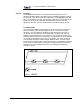
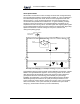
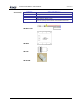
In-Hancer Plus BDA USER MANUAL Off-Air Operation BDA's Off-Air BDA's are intended to extend coverage into areas with coverage deficiency such as inside office buildings, shopping malls, hospitals, etc. They are designed to be located independently of the donor site and must be equipped with their own antenna systems - one to communicate with the donor site and the other(s) to communicate with portables in the shadow zone. A typical in-building coverage extension system is shown below.
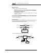
In-Hancer Plus BDA USER MANUAL Modular Construction The basic In-Hancer Plus BDA building blocks are. • • • • RF-Deck: an Amplifier and Controller assembly mounted on a heat-sink ready to install in an enclosure or rack. These include RF output Isolators. Enclosure including Power Supply. Optional Batteries for backup. Filter Kit including Duplexers, Filters and mounting hardware, if not already included in base Model.
In-Hancer Plus BDA Standard Models USER MANUAL MODEL DCM000000105 DESCRIPTION ENCLOSURE UHF MODELS Note that UHF Models DO NOT include Filtering and Duplexing. See the standard Filter Kits on the next page.
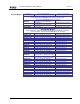
In-Hancer Plus BDA Filter Kits USER MANUAL KIT MODEL DCM000000105 DESCRIPTION UHF Filter Kits SB400-F1 SB400-F2L SB400-F2H1 SB400-F2H2 SB400-F2H3 SB400-F3 SB400-F4L SB400-F4H1 SB400-F4H2 SB400-F4H3 SB400-F5 UHF Filter Kit for any gain, 380-512MHz, 1MHz Bandwidth, 5MHz Tx/Rx Separation. (Large Encl only) UHF Filter Kit for up to 40dB gain, 406-512MHz, 1.5MHz Bandwidth, 3MHz Tx/Rx Separation. (Large Encl only) UHF Filter Kit for up to 80dB gain, 406-430MHz, 1.5MHz Bandwidth, 3MHz Tx/Rx Separation.
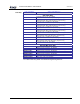
In-Hancer Plus BDA Accessories MODEL SB-BATT-CAB SB-DB15 SB-LITE SB-GLAND USER MANUAL DCM000000105 DESCRIPTION Battery Cable DB15 Breakout Kit (SB-ENCL-01 & -02 only) External Status Indicator Lamp to be mounted on front of Enclosure Cable Gland for Wires or Fiber. There are openings on the bottom of the Enclosures for these. SB-BATT-CAB SB-DB15 SB-LITE SB-GLAND Printed: 03.10.
In-Hancer Plus BDA Accessories for Stainless-Steel Weather-Resistant Enclosures USER MANUAL DCM000000105 Data Connectors & Cables For the Stainless-Steel Weather-Resistant Enclosures, if RS232 or User I/O connections are needed outside of the enclosure, then weather-resistant connections are required. These are available through cables that mount inside the enclosure, connect to the RF Deck's Control Board, and then to gasketed 8-pin connectors that mount on the enclosure bottom.
In-Hancer Plus BDA USER MANUAL DCM000000105 AC Power Accessories The AC Power is brought into the Stainless-Steel Enclosure via a water-tight cable that is included with the In-Hancer Plus BDA. Optional Accessories include... Printed: 03.10.
In-Hancer Plus BDA USER MANUAL DCM000000105 Accessory Installation For the Stainless-Steel Weather-Resistant Enclosures, most external accessories install on the bottom, except for the SB-LITE which mounts on the door. There are openings on the bottoms of the Enclosures for 4 Data Connectors and two of optional SB-GLAND. When not used these openings are sealed with weatherresistant plugs... Replacements for these may be ordered as Kaval Part SB-PLUG. Printed: 03.10.
In-Hancer Plus BDA Fiber Optic Options MODEL SB-FIB13 Fiber-Optic I/F SB-FIB13W Fiber-Optic I/F SB-FIB15 Fiber-Optic I/F SB-FIB15W Fiber-Optic I/F USER MANUAL DCM000000105 DESCRIPTION RF over Fiber Interface Module, Dual-Fiber 1310 nM Laser RF over Fiber Interface Module, Single-Fiber (WDM) 1310 nM Laser RF over Fiber Interface Module, Dual-Fiber 1550 nM Laser RF over Fiber Interface Module, Single-Fiber (WDM) 1550 nM Laser These are Factory Installed Options.
In-Hancer Plus BDA Installation USER MANUAL DCM000000105 In-Hancer Plus BDA Enclosures There are four standard BDA Enclosures, 2 sizes (Large and Small) of Painted Enclosures suitable for use in Electrical Rooms, and 2 sizes (Large and Small) of Stainless-Steel Enclosures which are sealed for enhanced Weather / Water Resistance. Painted Enclosure Photo is TBD Un-Packaging Each In-Hancer Plus BDA is carefully packaged for air shipment.
In-Hancer Plus BDA USER MANUAL DCM000000105 Mounting the In-Hancer Plus BDA The physical installation is accomplished by mounting the enclosure onto a vertical wall. Ensure that the unit is mounted in the upright position, as indicated by the upright Kaval Wireless Technologies’ logo. Using four mounting lugs on the enclosure as a template insert four bolts to the wall. Make sure the bolts are capable of supporting the weight.
In-Hancer Plus BDA USER MANUAL DCM000000105 The Small Stainless Steel Enclosure may also be mounted onto an optional Mounting Plate for quick installation and replacement... This is especially important in Subway Tunnel applications... Printed: 03.10.
In-Hancer Plus BDA USER MANUAL DCM000000105 Connections In-Hancer Plus BDA Connectors are on the bottom of the enclosure. RF cables can be connected to these connectors using RF cables as follows. Connect the in-building Distributed Antenna System cable to the Uplink port. Connect the Donor Site cable to the Downlink port. Connect AC Power. Connect any Data Cables. AC Power and RF Connections should be installed with all standard installation practices for lightning protection.
In-Hancer Plus BDA RF Deck Connections USER MANUAL DCM000000105 As previously described, the core of an In-Hancer Plus BDA is the RF Deck. The diagram below shows the RF Deck, its Indicators and Connectors... RS232 Connectors: RS232 Port #1 is for connecting directly to a PC via a straight-through male to female DB9 cable. The PC interface is described later. RS232 Port #2 is for special software defined interfacing.
In-Hancer Plus BDA USER MANUAL DCM000000105 The +28V Power is current limited to about 0.5 ampere maximum. The Form-C Fault Relay is rated at 30 VDC 30 VAC @ 0.5 Amp. For the CAN Network wiring, refer to the DCM000000103 CAN Wiring Guide. The three Auxiliary Inputs are intended for connection to external contact-closures connected between the input and ground. Each one, if closed, will create a Fault Condition Auxiliary Input #1 is also available at connector J19.
In-Hancer Plus BDA Battery Backup USER MANUAL DCM000000105 If the In-Hancer Plus BDA is being used without a Battery it must be configured to NOT use a battery. Without a battery the BDA will shut down or reset with any disruption to the AC power. When power is re-established the system will restart automatically within 30 seconds. External batteries may be connected using the SBBATT-CAB Battery Cable. The BDA has a built-in battery charger that will automatically recharge the attached battery.
In-Hancer Plus BDA In-Hancer Plus BDA Specifications USER MANUAL Frequency Bands Passband Ripple (Typical) Gain Range (Typical) Digital Gain Adjustment AGC (Power Levelling) AGC Dynamic Range RF Power 3'rd Order Intercept Point IP3 Noise Figure Propagation Delay Impedance VSWR Maximum RF Input Primary Power Optional Secondary Power / Battery Backup Dimensions W x H x D (incl.
In-Hancer Plus BDA Carrier De-Rating USER MANUAL DCM000000105 There are two requirements for the de-rating of RF Carriers in a multiple channel environment; one is Intermodulation - signals produced from non-linear effects between the intended channel signals. This intermodulation may cause interference to receiving equipment. In order to minimize Intermodulation signals, Power derating must be applied. In the USA there are FCC Intermodulation Specifications published in the EIA Standard PN2009.
In-Hancer Plus BDA Indicators USER MANUAL DCM000000105 The three LED Indicators on the RF Deck are... POWER: FAULT: AGC: This LED will be GREEN when the BDA is operating. This LED will light AMBER for any Fault Condition. This LED will light AMBER when the Power Limiting is on. The optional SB-LITE External Lamp indicates... Normal Operating Conditions: Fault Conditions: Loss of all Power: Lighted Steadily. Flashing Off The In-Hancer Plus BDA continuously performs internal diagnostics.
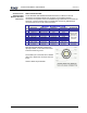
In-Hancer Plus BDA Configuration USER MANUAL DCM000000105 It is possible to re-configure an In-Hancer Plus BDA in the field, either with a Personal Computer (PC) or via the optional LinkNet Gateway Module. To use a PC it is necessary to use a straight-through DB9 male to female cable to connect the RS232 Port #1 DB9 connector on the RF Deck to a standard DB9 RS232 Connector on the PC. On the PC a terminal emulation program such as HyperTerminal is used to communicate to the In-Hancer Plus BDA.
In-Hancer Plus BDA Antenna Installation • • USER MANUAL DCM000000105 All Antenna Installation to be performed by Qualified Technical Personnel only. Antenna Installation Instructions and locations below are for the purpose of satisfying FCC RF Exposure Compliance requirements. • The Roof Top Antenna or Antennae for linking to the Donor Site(s) is/are directional (high gain) Antennae, fixed-mounted physically on the side or top of a building, or on a tower.
In-Hancer Plus BDA FCC Information to Users • USER MANUAL DCM000000105 This equipment has been tested and found to comply with the limits for a Class A digital device, pursuant to Part 15 of the FCC Rules. These limits are designed to provided reasonable protection against harmful interference when the equipment is operated in a commercial environment.
In-Hancer Plus BDA Maintenance & Safety USER MANUAL DCM000000105 The In-Hancer Plus BDA has been engineered for easy maintenance and for safe operation. This has been achieved as follows: The BDA provides fault monitoring and accurate status reporting. The 28V DC Power-supply is over-rated for actual requirements. Amplifiers are monitored for both Over-current and Under-current (most failures are sensed this way). Cabinet temperature is monitored for excessive temperature.