SPECTRIAN MCPS2135 SERIES MCPA MultiCarrier Amplifier Systems INSTALLATION & OPERATION MANUAL July 2001
IntroductionPlanning and PreparationIntroduction 2001 Spectrian Corporation. This document contains proprietary information of Spectrian Corporation . No part of this manual may be copied or disclosed without written authorization of Spectrian Corporation. All rights reserved. ii MCPS2135 Operations Manual 2001 Spectrian Corporation. All rights reserved.
IntroductionPlanning and PreparationIntroduction TABLE OF CONTENTS 1 2 Introduction .................................................................................................................................................11 1.1 About this Manual...............................................................................................................................11 1.2 Safety Information .....................................................................................................
IntroductionPlanning and PreparationIntroduction 4.4 5 MCPS2135 System Monitoring ............................................................................................................2321 5.1 Introduction......................................................................................................................................2321 5.2 Monitoring the MCPS2135 System Operation ..........................................................................2321 5.3 Alarm Definitions...........
IntroductionIntroduction 1 Introduction Chapter 1 introduces the MCPS2135 Series of Multi Carrier Power Amplifier (MCPA) Systems. It describes structure of this manual and introduces the different MCPS2135 Series amplifiers. 1.1 About this Manual The following manual describes how to install, operate, and maintain the MCPS2135 series of amplifiers. It is arranged into the following sections.
IntroductionPlanning and PreparationIntroduction Throughout this manual, notes, cautions and warnings are used with this convention: . Note: Suboptimal or out-of-specification performance will result from not following the instructions presented in ‘notes’. ∗ + Caution: Follow ‘caution’ notes to avoid possible damage to equipment. Warning: Injury to personnel, equipment fire, or other hazardous situations will result from not properly following ‘warning’ instructions. 1.
IntroductionPlanning and PreparationIntroduction Modulation Formats The MCPS2135 can amplify any number of signal carriers using AMPS, CDPD, IS-136 TDMA, IS-136HS GSM, IS-136HS EDGE, or IS-95 CDMA modulation up to the maximum rated system output power. Modularity The MCPS2135 family is designed for operation with 1 to 4 amplifier modules, each providing up to 135 Watts of RF output power (exclusive of combining losses).
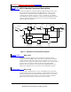
IntroductionPlanning and PreparationIntroduction 1.1.11.3.1 MCPA Module Functional Description To achieve the high level of linearity required to support multiple cellular carriers at the minimum cost, the RF modules in the MCPS2135 use a single loop feedforward correction architecture with two amplification paths – the main path, containing the main amplifier, and the error path, containing the error amplifier.
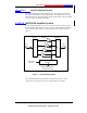
IntroductionPlanning and PreparationIntroduction 1.1.1.31.3.1.3 Amplifier Management Unit The Amplifier Management Unit (AMU) monitors and controls performance of the various subassemblies within the RF module. The AMU provides operating status information via front panel LEDs. Within a multi-module system, the AMU provides status to the MCPS2135 AMM. 1.1.21.3.2 MCPS2135 Amplifier System A fully-equipped MCPS2135 consists of a rack-mounted shelf containing up to four RF modules.
IntroductionPlanning and PreparationIntroduction Power Dimensions Comments (W x D x H) 135W 5.25” x 18” x 14” Single module with communication interface 135W 19” x 18” x 3 RU Single module configuration in 19 in. housing 135W 23” x 18” x 3 RU Single module configuration in 23 in.
Planning and PreparationPlanning and PreparationIntroduction 2 Planning and Preparation 2.1 Installation Planning It is important to ensure proper planning and site preparation is complete prior to beginning the installation of the MCPS2135. The following sections describe installation considerations and the information required before beginning the installation procedure. Spectrian Applications Engineering is always available to assist with planning for the installation of the MCPS2135. 1.22.
Planning and PreparationPlanning and PreparationIntroduction with viewing the status LED indicators on the front panel. The MCPS2135 should be oriented or shielded so that direct sunlight does not fall upon the front panel. Fire Protection Spectrian recommends that the MCPS2135 installation site be equipped with smoke detectors and an automatic fire-extinguishing system. In addition, for personnel safety, the site should be equipped with a portable halon or CO2 fire extinguisher.
Planning and PreparationPlanning and PreparationIntroduction 1.1.32.2.3 Cable Connections DC Power Supply The MCPS2135 requires customer-supplied connections to the site +27 VDC power supply. The MCPS2135 is normally connected to the power supply with a separate connection for each RF module; a single connection to each shelf is also possible using the optional shelf power bus.
Planning and PreparationPlanning and PreparationIntroduction Radio Parameters To set up the MCPS2135, the installer must know the following radio parameters for the MCPS2135 installation.
Planning and PreparationPlanning and PreparationIntroduction RF Drive Power Worksheet A) Total output power (POUT) required = W dBm B) Determine total output required for each fully loaded CDMA Frequency Assignment (FA): # of FA’s = total power per FA = total CDMA power (PCDMA) = Total available analog power (PAN ) = W (PAN = POUT – PCDMA) D) Total # of analog channels, including setup (#ch) = E) Maximum per channel analog output power (PAN/ch) = W dBm (PAN/ch = PAN/# of channels) F) System Gain
Planning and PreparationPlanning and PreparationIntroduction After verifying the power of each individual channel individually, ensure that the total average input power remains less than or equal to the maximum rated composite power calculated in (G) of the worksheet. 1. Key-on all channels at one time, including any CDMA F.A.s, and measure input power. 2.
Planning and PreparationPlanning and PreparationIntroduction • Work gloves • Steel-toe shoes • Back-support belt Tools • Box knife • Pair of large scis sors • Inspection flashlight or lamp • Pen or pencil • Strap cutter • Straight-blade screwdriver Other Materials • A copy of the Purchase Order • A copy of the Packing List Unpack equipment 1. Open the shipping container(s) and inspect the contents.
Planning and PreparationPlanning and PreparationIntroduction 2.4.3 Repackaging for Return Shipment If it is necessary to repackage the MCPS2135 for return shipment, contact Spectrian Customer Service for detailed instructions. If possible, use the original cartons and inserts to package equipment for return. Otherwise, use suitable shipping cartons and foam inserts to prevent damage in transit. 14 MCPS2135 Operations Manual 2001 Spectrian Corporation. All rights reserved.
MCPS2135 InstallationPlanning and PreparationIntroduction 3 MCPS2135 Installation 3.1 Introduction The following section describes how to install the MCPS2135 series amplifier in a base station. Each MCPS2135 system features rear-access RF input and output connectors, a DC voltage input receptacle, and a front-access RS-232 status interface connector. Additional optional features include a rear-access RS-422 serial interface connector and a remote alarms interface connector.
MCPS2135 InstallationPlanning and PreparationIntroduction • Cable Cutter (Klein 63050) • Flat and Phillips screwdrivers • Adjustable wrench • ESD protective wrist strap • Inspection lamp or flashlight • Crimping tool (T & B TBMS or equivalent) • Digital Volt Meter (DVM) • Torque Driver (Mountz TLS1360 or equivalent) • Current Meter • Wire Strippers (Greenlee 45109 or equivalent) Materials • Pressurized can of spray-on contact cleaner • Rack-mounting hardware and fasteners • DC Power
MCPS2135 InstallationPlanning and PreparationIntroduction 4. Unpack the MCPS2135 shelf and record its serial number. Ensure the shelf is in the proper upright vertical orientation and slide it onto the mounting rails. 5. Use the supplied mounting screws to attach the shelf to the rack. Tighten rack mounting screws securely. 3.3.2 Install Modules in Shelf 1. Unpack each RF module.
MCPS2135 InstallationPlanning and PreparationIntroduction with local building codes and industry practice. Refer to Table 2 for the recommended power supply circuit and wire sizing for each option. + ∗ WARNING: Do not perform DC lead installation with energized leads. Ensure that the DC power supply is OFF for all installation activities! 1. Locate the positive and negative terminals on the customer-provided DC power source, and verify polarity with a DVM. 2.
MCPS2135 InstallationPlanning and PreparationIntroduction 2. Locate the female N-type RF connector labeled “RF OUTPUT” on the MCPS2135. 3. Screw the male cable connector firmly onto the female RF output connector of the MCPS2135. 4. Locate the male input RF connector on the end of the coaxial cable from the RF signal source. Inspect the connector for damage or irregularity, and fix any problems with the cable or connector before proceeding. 5.
System Start-UpPlanning and PreparationIntroduction 4 System Start-Up 4.1 Introduction This section contains instructions on powering up the MCPS2135 amplifier system. These procedures should be followed after installing the MCPS2135 amplifier system in the rack. 1.24.2 Safety Information and Tools To avoid injury, installers, technicians, and maintenance personnel must follow Spectrian's recommended procedures and observe safety precautions. + + .
System Start-UpPlanning and PreparationIntroduction 4. + If used, verify that the MCPS2135 address is set correctly. WARNING: The RF output of the MCPS2135 should be connected to a 50-ohm load before DC power is turned on. The load must be capable of dissipating at least 500 watts average power and 6,300 watts of peak power. After mechanical and electrical installation tasks are complete, the MCPS2135 is ready for power-on check. 1.44.4 ∗ .
MCPS2135 System MonitoringPlanning and PreparationIntroduction 5 MCPS2135 System Monitoring 5.1 Introduction This section describes methods for monitoring the MCPS2135 amplifier system operation. 1.25.2 Monitoring the MCPS2135 System Operation The MCPS2135 Amplifier Management Module (AMM) has a front panel RS-232 status port. This port provides the option to monitor the operation and status of the MCPS2135 using a laptop computer, if desired.
MCPS2135 System MonitoringPlanning and PreparationIntroduction 1.1.1.35.3.1.3 Critical Alarm A major failure or a condition exists that could result in damage. The MCPS2135 is automatically taken out of service. Immediate service attention is required. 1.1.25.3.2 Alarm Responses The fault management system automatically responds when a fault is detected. Responses vary in impact from alarm notification with no subsequent action (for minor faults) to alarm notification and shut-down (for critical faults).
MCPS2135 System MonitoringPlanning and PreparationIntroduction 1.45.4 MCPS2135 Alarm Limits and Protection Circuits The MCPS2135 series of multicarrier power amplifiers has a wide range of alarm configurations available. These may be specified to meet the demands of specific applications. In addition, the MCPA modules have built-in protection circuits to prevent damage from unintentional misuse. Module alarms may be summarized and reported to a BTS using a customized interface.
MCPS2135 System MonitoringPlanning and PreparationIntroduction 1.1.25.4.2 MCPA Module Alarms The set points, delay, reset points, and latching conditions of all three types of alarms are software configurable. Some Minor alarm settings can be specified by the customer but must be agreed upon between the customer and Spectrian prior to installation or modification. Alarm limits for Major and Critical Alarms are fixed and can not be modified, insuring long term reliability of the MCPA module.
MCPS2135 System MonitoringPlanning and PreparationIntroduction 1.1.35.4.3 MCPA System Alarms A multimodule MCPA system will have an Amplifier Management Module (AMM) that summarizes the status of all modules and reports this information to the base transceiver station (BTS). The format of this information is usually customized for specific customers. Options for physical layer customization include: • Parallel TTL Interface – Summary bits for individual module status.
Troubleshooting and MaintenancePlanning and PreparationIntroduction 6 Troubleshooting and Maintenance 6.1 Introduction The following chapter provides basic information about diagnosis of problems with the MCPS2135. Please read the following safety information prior to beginning diagnosis and repair actions. + . Warning: Troubleshooting and repairs should be performed only by trained and qualified personnel or at authorized Spectrian repair depots.
Troubleshooting and MaintenancePlanning and PreparationIntroduction cautious in handling test leads, tools, and equipment near live circuits. Never reach into an enclosure for the purpose of servicing or adjusting live equipment. 6.2 Troubleshooting Refer to section 5.3 for a definition of alarm types and the significance of those alarm types. 1.1.16.2.1 Using LED Indicators Each MCPS2135 RF Module is equipped with four LED indicators mounted on the front panel.
Troubleshooting and MaintenancePlanning and PreparationIntroduction 6.3 Periodic Maintenance 6.3.1 Dust Removal Keep the air inputs and outputs of the MCPS2135 free of dust or other material that could block cooling airflow. 1.1.26.3.2 Visual Inspection Periodically visually inspect the MCPS2135 to ensure that all indicators are functioning normally and that all system interfaces are properly connected. 1.46.
Troubleshooting and MaintenancePlanning and PreparationIntroduction 5. Slide the new AMM into the shelf sub-assembly. 6. Fasten the AMM front panel fastener. 7. Turn on the DC power to the MCPS2135. The system will perform a powerup self-test automatically. 8. The POWER LED will be GREEN. 6.4.3 Replacing shelf subassembly + + ∗ + . Warning: Turn off the DC voltage and RF power prior to replacing an MCPS2135. Warning: Remove all DC and RF connectors prior to removing the MCPS2135 from the rack.
Troubleshooting and MaintenancePlanning and PreparationIntroduction 4. Remove the screws securing the fan module to the RF module. 5. Disconnect the wiring harness from the fan module. 6. Connect the harness to the new fan module. 7. Replace the fan module and replace the attachment screws. 8. Replace the RF module in the rack. 9. Enable the module. Following the automatic power-up reset sequence, the FAN indicator LED should be GREEN. MCPS2135 System Operation 2001 Spectrian Corporation.
Appendix A1 Spectrian, Inc. OfficesPlanning and PreparationIntroduction Appendix A1 Spectrian, Inc. Offices Spectrian Headquarters 350 West Java Drive Sunnyvale, Calif. 94089 Ph: Fax: 408-745-5400 408-541-0263 Web: www.spectrian.com Spectrian, Asia Office 4TH FL.
Appendix A2 Major Electrical SpecificationsPlanning and PreparationIntroduction Appendix A2 Major Electrical Specifications Major Equipment Specifications for the MCPS2135 Amplifier System Electrical Specifications Frequency Range Average Power¹ into 50 Ohms Intermodulation Distortion (IMD) CDMA Adjacent Channel Power2 @ 881 MHz, 100W Output Receive Band Noise Carrier Spacing (AMPS/TDMA) Specification @ 25ºC 869 - 894 MHz 135W (51.3 dBm) to 500W (57.
Appendix A3 Major Mechanical SpecificationsPlanning and PreparationIntroduction Appendix A3 Major Mechanical Specifications Mechanical Specifications Operating/Storage Temperatures 0ºC to 50ºC/-40ºC to 85ºC Size, 4 module shelf (Excludes mounting ears and handles). (D x W x H) 17.72 x 21.56 x 13.97 in. max (450 x 547.62 x 354.84 mm max.) Size, 1 module shelf (Excludes mounting ears and handles). 17.72 x 17.0 x 5.25 in. max (450 x 431.72 x 133.33 mm max.
Appendix A3 Major Mechanical SpecificationsPlanning and PreparationIntroduction Mechanical Outlines MCPS2135 500W MCPS2135 System Operation 2001 Spectrian Corporation. All rights reserved.
Appendix A3 Major Mechanical SpecificationsPlanning and PreparationIntroduction MCPS2135 135W Configuration 36 MCPS2135 Operations Manual 2001 Spectrian Corporation. All rights reserved.
Appendix A3 Major Mechanical SpecificationsPlanning and PreparationIntroduction MCPA Module for MCPS2135 Family MCPS2135 System Operation 2001 Spectrian Corporation. All rights reserved.
Appendix A4: MCPS2135 System CheckoutPlanning and PreparationIntroduction Appendix A4: MCPS2135 System Checkout MCPS System Checkout In some cases, it may be desirable to perform a system checkout prior to installation to insure proper operation. The following procedure is included here only for reference. Accurate specification verification is not guaranteed when using this procedure.
Appendix A4: MCPS2135 System CheckoutPlanning and PreparationIntroduction Performance Checkout Procedure 1. Set current limit on Sorenson power supply to appropriate level as listed in Table 2. 2. Set DC voltage to 27 ± 1V. 3. With no RF applied, verify that idle current is approximately 13A x number of MCPA RF modules. 4. Apply RF signal, and slowly increase power to maximum rated power as listed in Appendix A2. 5. Verify that the total DC current is approximately that listed in Table 2. 6.
INDEXPlanning and PreparationIntroduction 7 INDEX acoustic treatment 8 combiner airborne dust air-conditioning alarm configurations 8 8 23 active combiner losses output alarm connection Alarm Definitions alarm output 9 21 combustible materials floor covering composite power connection alarm/protection hierarchy ambient noise 18 23 8 cooling air critical faults definition AMM installation replacement 6 16 28 customer service contact information DC input voltage range Amplifier Management Modu
INDEXPlanning and PreparationIntroduction Graphical User Interface ground halo site grounding system site 3, 21, 23 8 8 guides module alignment hot air 16 exhaust hot-swappable RF modules 8 28 input drive level worksheet installation lighting working area lightning arrestors lightning protection main loop major faults Periodic Maintenance physical layer alarms 28 pinout RS232 planning site positive supply connecting 25 33 7 17 19 20 26 7 diagnosis protection circuits built-in 1 3 3 radio para
INDEXPlanning and PreparationIntroduction smoke detectors summarized alarms uncrating unrestricted airflow 42 8 23 12 8 vibration Warning definition weight wrist strap 8 2 7 13, 15 MCPS2135 Operations Manual 2001 Spectrian Corporation. All rights reserved.