
User's Manual

Introduction
4 MCPS4080 Operations Manual
2001 Spectrian Corporation. All rights reserved.
qualified service technicians, greatly reducing service shipping costs and turn-
around time.
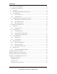
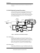
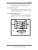
1.3.1 MCPA Module Functional Description
To achieve the high level of linearity required to support multiple PCS carriers at
the minimum cost, the RF modules in the MCPS4080 use a single loop feed-
forward correction architecture with two amplification paths – the
main path
,
containing the main amplifier, and the
error path
, containing the error amplifier.
The combination of these two paths in a feed forward loop configuration results in
a signal in which the distortion products have been cancelled, enabling highly
linear operation of the amplifier.
Figure 1: RF Module Functional Block Diagram
1.3.1.1 Main Loop
The output of the main amplifier contains both the desired signal and Inter-
modulation Distortion (IMD) products. This signal is coupled off and combined
with the undistorted input signal coupled off the preamplifier. The relative delay
and phases of these signals are adjusted so they combine to cancel out the desired
signal, creating an error signal composed of only the main amplifier IMD
products. The cancellation process is controlled by a Digital Signal Processor,
which insures optimum carrier cancellation over all environmental conditions.
1.3.1.2 Error Loop
The error signal is amplified in the error loop. The amplified error signal is then
combined with the output of the main amplifier containing both the desired signal
MainPath
Phase/Amplitude
Control
Main Amp
Delay Filter
Output Module
Pilot
Generator /
Reciever
Amplifier
Manangement
Unit
Carrier
Cancellation
Error Path
Σ
τ
Preamplifier
Delay
Line
Error Amp
RF Input
RF Output
Phase/Amplitude
Control