
User's Manual


Troubleshooting and Maintenance
MCPS4080 System Operation 29
2001 Spectrian Corporation. All rights reserved.
5.
Slide the new AMM into the shelf sub-assembly.
6.
Fasten the AMM front panel fastener.
7.
Turn on the DC power to the MCPS4080. The system will perform a power-
up self-test automatically.
8.
The
POWER
LED will be GREEN.
6.4.3 Replacing shelf subassembly
!
Warning: Turn off the DC voltage and RF power prior to replacing an
MCPS4080.
!
Warning: Remove all DC and RF connectors prior to removing the MCPS4080
from the rack.
☛
Caution: Do not attempt to move an MCPS system with modules installed.
1.
Remove the RF Modules’ front panel retaining screws.
2.
Remove the RF modules from the rack.
!
WARNING: The RF Module is very heavy (50 lbs / 22.7 kg). Get assistance if
necessary.
3.
Set each RF Module aside in a clean, safe place, free of electrostatic charges.
4.
Remove the rack retaining screws. Grasp the front panel with both hands and
pull the MCPS4080 straight out from the rack.
5.
Set the disconnected MCPS4080 aside in a clean, safe place, free of
electrostatic charges.
6.
Remove the replacement MCPS4080 from its static-protective packaging.
✎
Note: You may wish to record the serial number on your repair record before
installing the module.
7.
Follow the installation and operation instructions in Sections 3 and 4 to place
the unit back in service.
6.5 Module Service
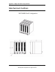
6.5.1 Replacing MCPS4080 Fan Modules
!
WARNING: The RF Module is very heavy (50 lbs / 22.7 kg). Get assistance if
necessary.
☛
Caution: Provide bottom support when removing an MCPA module to avoid
damage to the fan housing.
1.
Disable the RF module with the failed fan.
2.
Remove the RF module with the failed fan from the rack.
3.
Place the RF module on a clean, static-free work surface.
4.
Disconnect the fan power cable.