LinkNet Satellite Unit (LSU) RF - FIBER Interface Modules User Manual Installation, Operation And Maintenance KAVAL WIRELESS TECHNOLOGIES 60 Gough Road Markham, Ontario, L3R 8X7 Telephone: (888) 86-KAVAL Web: www.kaval.com E-mail: info@kaval.com Document #DCM000000052, Rev.
SatelLink z USER MANUAL DCM000000052 PROPRIETARY STATEMENT © 2000 KAVAL WIRELESS TECHNOLOGIES All rights reserved. No part of this publication, or any software included with it may be reproduced, stored in a retrieval system, or transmitted in any form or by any means, including photocopying, electronic, mechanical, recording or otherwise, without the prior written permission of the copyright holder.
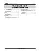
SatelLink z USER MANUAL DCM000000052 TA B L E O F CONTENTS 1. LSU MODULES ........................................ 4 OVERVIEW ............................................................. 4 Theory Of Operation......................................... 4 MODELS................................................................. 4 BLOCK DIAGRAMS .................................................. 5 LSU Head-End Module..................................... 5 LSU Remote Module ....................................
SatelLink z USER MANUAL 1. LSU MODULES Overview Theory Of Operation The LSU RF to Fiber Modules provide a multi-band, multi-service link from a main distribution center to multiple local antennae. RF Signals are distributed in runs of three pairs of Single-Mode Fiber-Optic Distribution Lines, organized as... Fiber Pair #1: Fiber Pair #2: Fiber Pair #3: 1.9 GHz PCS Services 800 MHz Cellular Services 800 MHz iDEN, Public Safety, & Paging Services There are two models....
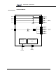
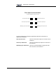
SatelLink z USER MANUAL Block Diagrams LSU Head-End Module RF Out #1 RF Out #2 RF Out #3 SM F.O. In (PIN Diodes) RF Out #4 PreAmps RF Input Laser Diode SM F.O. Out (Lasers) PreAmp Power Supply 120 / 240 VAC 120/240 VAC Printed: 03.06.
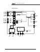
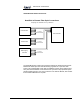
SatelLink z USER MANUAL LSU Remote Module 1.9 GHz 1.9GHz 869-894 MHz Cellular Four Antenna Ports 928-941 MHz PreAmp 1.9GHz Loose Couplers 1.8 GHz Cellular 824-849 MHz Notch 851+ IDEN & 806-824 MHz Notch 894- SM F.O. Out (Lasers 800-900MHz 851-869 MHz IDEN & SM F.O. In (PIN 1.9GHz PreAmp 2 RF Ports to Antennae on Alternate 899-902 MHz RF Monitor FO Current & Power Monitors Ports MicroCircuitr Power Supply 120 / 240 Green Power On Red Fault LED CAN To Head- 24 VDC Printed: 03.
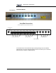
SatelLink z USER MANUAL Connections LSU Head-End Module Head-End Connections SC/APC SingleMode Fiber-Optic & SMA RF Connectors AC Power Cord TX1 TX2 TX3 Downlink Optical Outputs TX4 RX1 RX2 RX3 RX4 TX In RX1 RX2 RX3 RX4 Uplink RF Outputs Uplink Optical Inputs Downlink RF Input The Head-End has one Downlink RF Input providing the signal for four Downlink Optical Outputs, thus each Head-End Module services one and only one of the three Fiber-Pairs (PCS, Cellular, or iDEN/Trunking).
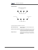
SatelLink z USER MANUAL LSU Remote Module Antenna Port Connections SMA Connections Four Direct Antenna Connections Downlink Sampler Port Uplink Sampler Port Two Expansion Antenna Connections The Remote Module has 8 SMA RF Connections.. Main Antenna Ports (4): Used to connect to four identical distributed indoor antenna systems.
SatelLink z USER MANUAL Fiber Optic Port Connections SC/APC SingleMode Fiber-Optic Connectors PCS Uplink Optical Output Cellular Uplink Optical Output iDEN/Paging Uplink Optical Output PCS Downlink Optical Input Cellular Downlink Optical Input iDEN/Paging Downlink Optical Input The Remote Module has 6 SC/APC Single-Mode Fiber-Optic Connections for cabling to the Head-End... PCS Up & Downlink: Used for the PCS Fiber-Optic Pair connection to the Head-End.
SatelLink z USER MANUAL LSU Head-End to Remote Interconnects Head-End to Remote Fiber-Optic Connections Groupings of 3 Head-Ends to every 4 Remotes PCS Head-End To 3 More Remote Modules Remote Module Cell Head-End To 3 More Remote Modules iDEN / Paging Head-End To 3 More Remote Modules The Single-Mode Fiber-Optic interconnections between the Head-End and Remote Modules are based upon the Head-Ends being organized on a "per Fiber-Pair" system.
SatelLink z USER MANUAL Module Specifications DCM000000052 Downlink: 851-869 MHz iDEN & Pub Safety 869-894 MHz Cellular 928-941 MHz Paging 1930-1990 MHz PCS Frequency Bands Uplink: 806-824 MHz iDEN & Pub Safety 824-849 MHz Cellular 896-902 MHz Paging 1850-1910 MHz PCS iDEN/Cell/Paging Combined: Maximum Power +35 dBm IP3 Typical from any one of eight PCS Combined: Remote Module Antenna Ports +33 dBm IP3 Typical Gains Downlink: +28 dB Maximum from any one of eight\ Remote Module Antenna (7 dB Gain Reducti
SatelLink z USER MANUAL Remote Module PerCarrier De-Rating DCM000000052 All signals that fall within a given Pass-Band range will “share” power amongst them. A multiple channel effect is Intermodulation - signals produced from non-linear effects between the intended channel signals. This intermodulation may cause interference to receiving equipment. In order to minimize Intermodulation signals, Power de-rating must be applied.
SatelLink z USER MANUAL Operation DCM000000052 Normal Operation The LSU Head-End Module has one LED on the faceplate: 1. OPERATING - Normally this LED will be GREEN. The LSU Remote Module has three LED’s on the faceplate: 1. OPERATING - Normally this LED will be GREEN. 2. FAULT – Red LED, If the internal diagnostics for the module detect a problem, then this LED will remain on 3. LASERS ON - This LED will be GREEN when any one of the three Lasers are operating.
SatelLink z USER MANUAL Laser Safety Printed: 03.06.19,16:02 DCM000000052 • Both the Head-End and Remote Modules have Class IIIb Laser Devices as Fiber-Optic Transmitters. • Under normal installation both Modules are intrinsically-safe (Class I) since the Fiber-Optic cabling will be installed.
SatelLink z USER MANUAL Antenna Installation • • • DCM000000052 All Antenna Installation to be performed by Qualified Technical Personnel only. Antenna Installation Instructions and locations below are for the purpose of satisfying FCC RF Exposure Compliance requirements. The In-Building Antenna connection is via a coaxial cable distribution system with Signal Taps at various points connected to the fixed-mounted Indoor Antennae. This is shown in the figure in the Introduction.