LinkNet™ LNKF800 RF MODULES USER MANUAL INSTALLATION, OPERATION AND MAINTENANCE KAVAL WIRELESS TECHNOLOGIES 60 Gough Road Markham, Ontario, L3R 8X7 Telephone: (888) 86-KAVAL Web: www.kaval.com E-mail: info@kaval.com Document #DCM000000014, Rev.
LinkNet™ LNKF800 RF MODULES ! USER MANUAL DCM000000014 PROPRIETARY STATEMENT © 2000 KAVAL WIRELESS TECHNOLOGIES All rights reserved. No part of this publication, or any software included with it may be reproduced, stored in a retrieval system, or transmitted in any form or by any means, including photocopying, electronic, mechanical, recording or otherwise, without the prior written permission of the copyright holder.
LinkNet™ LNKF800 RF MODULES ! USER MANUAL DCM000000014 TA B L E O F CONTENTS 1. LNKF800 MODULES ................................ 4 OVERVIEW .............................................................. 4 Theory Of Operation ......................................... 4 MODELS ................................................................. 4 BLOCK DIAGRAM ..................................................... 5 LNKF800 RF Module ........................................ 5 MODULE SPECIFICATIONS ...........
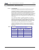
LinkNet™ LNKF800 RF MODULES ! USER MANUAL 1. DCM000000014 LNKF800 MODULES Overview Theory Of Operation An LINKNET FM MODULE is a radio repeater that simultaneously receives and transmits a single narrow band radio channel on exactly the same frequency. The LINKNET FM MODULE accomplishes its repeater function without store and forward circuitry, or expensive conventional simulcasting techniques.
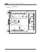
LinkNet™ LNKF800 RF MODULES ! USER MANUAL Block diagram RF Output 806-941 MHz DCM000000014 LNKF800 RF Module Transmit Board Gain Control IF Board Blind-Mate to SMA RF Connector First IF Filter Buffers, Filters, and Linear Power Amplifier Gain Control First Local Oscillator Test Oscillator 2'nd Local Oscillator 2'nd IF Crystal Filter UMC Controller Board MicroController with lines to all Boards Power Circuits Communication Interfaces Power & Control to Backplane 2'nd IF Crystal Filter Recei
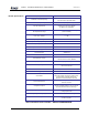
LinkNet™ LNKF800 RF MODULES ! USER MANUAL Module Specifications DCM000000014 Frequency Bands See Model Chart Narrowband FM, Modulation & Channel Spacing 25 or 12.5 KHz as per Model Chart RF Frequency Stability Tracks Input Signal Exactly +38 dBm for A1,B1,C2,D2 Models Max. RF Output Power RF Output Power Range +37 dBm for G1, H1 Models Power can be reduced 20 dB in 1 dB Steps (AGC Controlled) RF Output Power Variation vs.
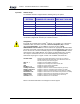
LinkNet™ LNKF800 RF MODULES ! USER MANUAL Operation DCM000000014 Software Set-up The LNKF800 module is shipped with the following factory set options: OPTION RANGE OF VALUES DEFAULT VALUE Frequency See Model Chart Order Specific Receive Threshold –110 to -50 dB -89 dB Receive Hysteresis 1 to 10 dB 2.5 dB Time Out 0 to 600 Seconds, or none 300 Seconds Module Enabled On / Off On Transmit Power Level 20 to 38 dBm Order Specific Default values may be changed when an order is placed.
LinkNet™ LNKF800 RF MODULES ! USER MANUAL DCM000000014 Power On Self Test (POST) Each system module automatically performs a self-diagnostics when inserted into the system Card-cage. These tests determine that the unit is a) correctly installed in the Card-cage and b) not damaged in transit. • • • • All six of the LED’s on the front panel will flash 3 times If the LED’s do NOT flash three times, then remove the module, check the power source, and re-insert the module, (See Installation Instructions).
LinkNet™ LNKF800 RF MODULES ! USER MANUAL DCM000000014 Normal Operation The LNKF800 Module has six LED’s on the faceplate: 1. OPERATING - Under normal operating conditions, this LED will flash GREEN when RF Data is present. 2. STANDBY – Under the control of the Controller Module, the LNKF800 Module has the ability to act as a duplex transmitter, sitting perpetually in Stand by Mode waiting for the primary transmitter to fail. This LED should be constant Amber.
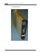
LinkNet™ LNKF800 RF MODULES ! USER MANUAL DCM000000014 LINKNET FM MODULE Module Printed: 01.10.
LinkNet™ LNKF800 RF MODULES ! USER MANUAL Antenna Installation • • • • • DCM000000014 All Antenna Installation to be performed by Qualified Technical Personnel only. Antenna Installation Instructions and locations below are for the purpose of satisfying FCC RF Exposure Compliance requirements. Note that if multiple LinkNet™ Modules are used, the Instructions below apply to the composite power output of all Modules when transmitting simultaneously.