
User's Manual


LinkNet™ LNKA800 RF MODULES ! USER MANUAL
DCM000000054
Printed: 01.05.08,16:18
Revision Date:5/8/01 6
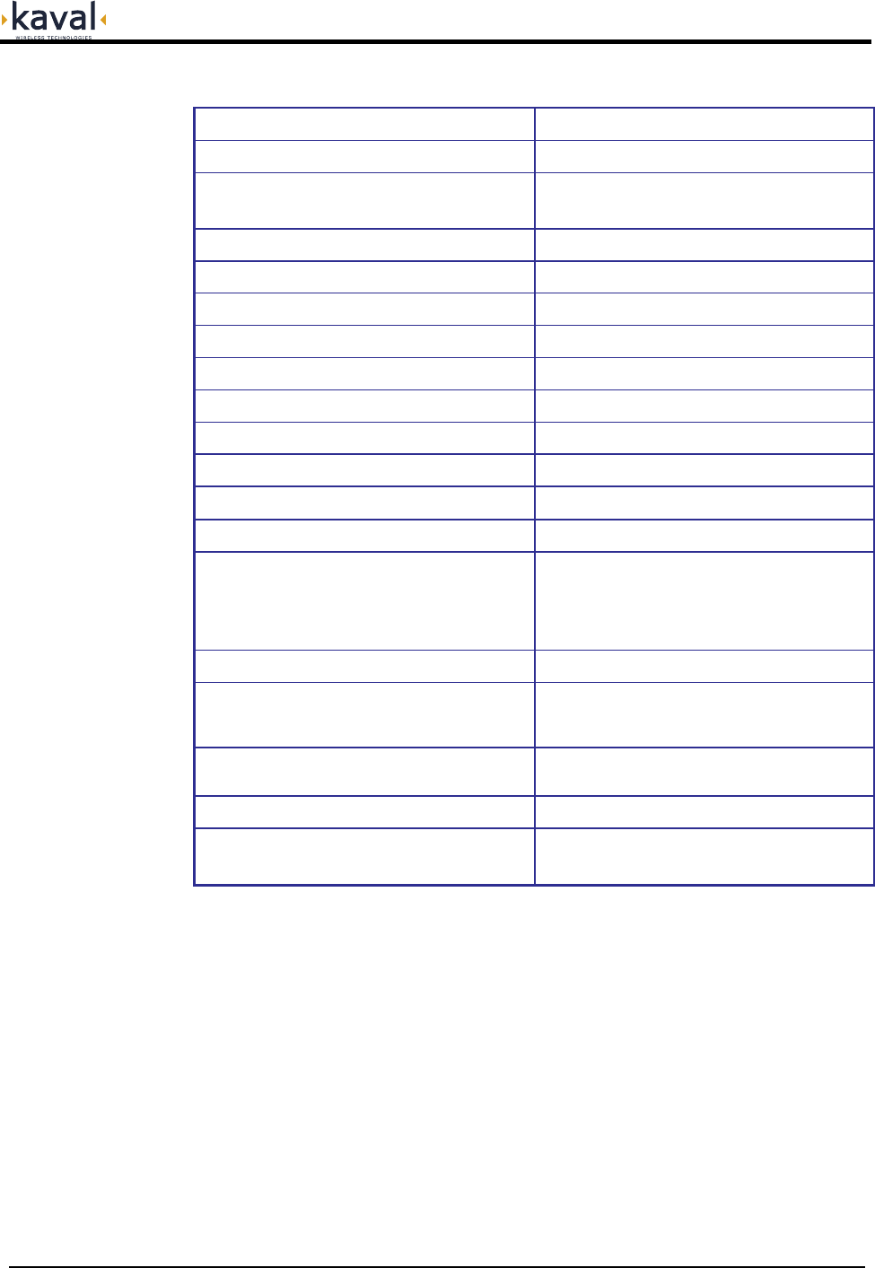
Frequency Bands See Model Chart
Modulation & Channel Spacing Broadband Amplifiers
RF Output Power Capability
1dB Compression Point = +37 dBm Typical
IP3 Intermodulation = +47 dBm Typical
AGC Control Adjustment Range +15 to +30 dBm or Disabled
Gain Adjustment Range +34 to +84 dB
Noise Figure <8 dB, 5 dB Typical
Maximum RF Input < +10 dBm without Damage
Transmit Duty Cycle Continuous
Transmit Spurious -13 dBm max
Receive Conducted Spurious -57 dBm Max
Group Delay <5 uS
RF Connectors
SMA (50Ω) Connectors on back of Card-Cage
Module Power Supply Requirements 40 Watts Maximum
Connections
Edge Connector & 2 Blind-Mate RF Connectors to
Card-Cage, DB-15 Connector on back of Card-
Cage provides per-Module Fault Relay,
Interconnect to other Modules, & RS-232
Connection
Front Panel Indicators Operating, Stand by, Fault, Program Mode
Configuration Options
RF Modules may be configured either via the
optional Controller Module, or via a PC and an
RS-232 Connection via the Card-Cage.
Operating Temperature Range
-10 to +50
o
C; Consult Kaval for installation specific
forced-air cooling requirements
Operating Humidity Range 10 to 90% RH, Non-Condensing
Size & Weight
9.11” High, 2.00” Wide, 14.00” Deep,
10 lbs, 4.5 kg Max
Module Specifications