User’s Manual ALR Compact Repeater VD203 67/EN - English Future on Demand.
ALLGON Systems AB ALR Compact Repeater User’s Manual ALR Compact Repeater Low Power Band Selective Repeater – English VD203 67/EN - User’s Manual Rev.
ALLGON Systems AB ALR Compact Repeater This document describes installation, commissioning and the design of the Allgon ALR Compact Repeater. Communication between the Allgon ALR Compact Repeater and an operator is carried out either by using Allgon OMT32 (Operation and Maintenance Terminal), or Allgon OMS (Operation and Maintenance System). OMT32 is described in the AR Repeaters and OMT32, User’s Manual. OMS is described in the Advanced Repeater OMS, User’s Manual.
ALLGON Systems AB ALR Compact Repeater Contents Abbreviations ............................................................................................................... 1. Safety ....................................................................................................................... v 2. Introduction 2-1 2-2 2-3 2-4 2-5 3. Installation ................................................................................................................
ALLGON Systems AB ALR Compact Repeater Board and Unit Descriptions ............................................................................. DCC - Directional Coupler for Compact ................................................... DPX - Duplex Filter ......................................................................................... BSC Band Selective Compact Board ......................................................... LNA - Low Noise Amplifier ................................................
ALLGON Systems AB ALR Compact Repeater Figures Figure 2-1. Allgon ALR Compact Repeater .............................................................. 2-1 Figure 2-2. Repeater coverage of shaded area ..................................................... 2-4 Figure 2-3. Repeater in sports arena ........................................................................ 2-5 Figure Figure Figure Figure Figure Figure Figure Figure 3-1. 3-2. 3-3. 3-4. 3-5. 3-6. 3-7. 3-8. Repeater dimensions .....................
ALLGON Systems AB ALR Compact Repeater Abbreviations Abbreviations used in this manual, in the software, and in the repeater: AGC AMPS BCCH BS BSC CDMA CW DCC DAMPS DCS DL DPX EEPROM EGSM ETACS ETSI GSM HW LED MS MSC NMT OMS OMS/PC OMT32 OMT32/PC PCN PCS PSM PTFE RCC RF RSSI RTC SW TACS TDMA UL UPS VD203 67/EN - User’s Manual Automatic Gain Control Advanced Mobile Phone Service Broadcast Control Channel (GSM broadcast channel time slot) Base Station, BS antenna = towards the base station Band Selective
ALLGON Systems AB ALR Compact Repeater Safety 1. Safety Any personnel involved in installation, operation or service of Allgon repeaters must understand and obey the following: • Allgon repeaters are designed to receive and amplify signals from one or more base stations and retransmit the signals to one or more mobile stations. Also, the repeaters are designed to receive signals from one or more mobile stations, amplify and retransmit to the base stations.
ALLGON Systems AB ALR Compact Repeater Safety Static Electricity Static electricity means no risk of personal injury but it can severely damage essential parts of the repeater, if not handled carefully. Parts on the printed circuit board as well as other parts in the repeater are sensitive to electrostatic discharge. Never touch the printed circuit board or uninsulated conductor surfaces unless absolutely necessary.
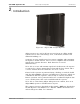
ALLGON Systems AB ALR Compact Repeater Introduction 2. Introduction Figure 2-1. Allgon ALR Compact Repeater Allgon repeaters are used to fill out uncovered areas in cellular mobile systems, such as base station fringe areas, road tunnels, business and industrial buildings, etc. A repeater receives signals from a base station, amplifies and retransmits the signals to mobile stations. Also it receives, amplifies and retransmits signals in the opposite direction. Both directions are served simultaneously.
ALLGON Systems AB ALR Compact Repeater Introduction Repeater Type The following repeater type is currently available: • Band selective repeater with adjustable bandwidth Band selective repeater with adjustable bandwidth The band selective compact repeater has filters that can be set to various bandwidths. This repeater type is used for analog or digital systems, such as NMT, GSM, TACS/ETACS, AMPS, DAMPS and CDMA. VD203 67/EN - User’s Manual Rev.
ALLGON Systems AB ALR Compact Repeater Introduction Using Repeaters In areas where the radio signal propagation is poor repeaters can be used to fill out those areas which are not covered by the base station.
ALLGON Systems AB ALR Compact Repeater Introduction Shaded Area A valley is shaded by hills. There is a base station 5 kilometers away, but the lowest signal strength in the valley is less than –100dBm. A mast used for other purposes is available for a repeater installation. The mast height is 42 meter and it is located on a hill. The scenario is illustrated in Figure 2-2. Donor antenna Service antenna Figure 2-2.
ALLGON Systems AB ALR Compact Repeater Introduction Sports Arena A 2000 spectators sports arena with metallic roof had an indoor signal strength too low to provide a fair service in most parts of the arena. The nearest base station was 8 kilometers away and it was equipped with one carrier only. A donor antenna directed towards the base station was mounted on a mast outside the building and a repeater was installed inside the building with the service antenna on the arch vault.
ALLGON Systems AB ALR Compact Repeater Installation 3. Installation Before installation, read carefully Chapter 1, Safety. Siting the Repeater Allgon repeaters are designed for outdoor usage. However, humidity and temperature changes may have affect on the reliability. A preferable site for the repeater is thus indoor, in a tempered and ventilated room.
ALLGON Systems AB ALR Compact Repeater Installation Dimensions and Weight The dimensions of the repeater, including the mounting bracket, is shown in Figure 3-1. The repeater chassis consists of two main parts, a cabinet in which the circuitry is housed, and a cover. Mounting bracket Cabinet Cover 385 (15.2") 15 (0.6") 385 (15.2") 110 (4.3") Figure 3-1. Repeater dimensions Approximately repeater weight Repeater with cover ...................................................................
ALLGON Systems AB ALR Compact Repeater Installation Mounting The ALR repeater is easy to mount, either by anchoring the repeater in the fixing holes, or by using the EA101 57/1 Pole Mounting Bracket kit, containing a mounting bracket, clamps for 40mm – 110mm round pole, and fixing screws for fastening the repeater to the mounting bracket. The mounting bracket is shown in the figure. The holes are threaded (M6) and correspond to the mounting holes in the repeater. 1. Mount the repeater.
ALLGON Systems AB ALR Compact Repeater Installation Figure 3-3. Attaching the bracket to a pole Figure 3-3 shows a bracket attachment to a pole using the mounting bracket and the clamps provided with the bracket. Figure 3-4. Attaching the bracket to a mast Figure 3-4 shows a bracket attachment to a mast using two angle irons and four M6 (1/4") screws. The screw heads can be slided into the bracket profile as shown in the figure. VD203 67/EN - User’s Manual Rev.
ALLGON Systems AB ALR Compact Repeater Installation LO HI ANT ANT HI LO Figure 3-5. Attaching the repeater to the bracket If the mounting bracket is used, then mount the repeater on the bracket using the four fixing screws provided with the mounting bracket kit (see Figure 3-5). 2. Mount the donor antenna directed towards the base station antenna. 3. Mount the service antenna directed towards the area to be covered by the repeater. VD203 67/EN - User’s Manual Rev.
ALLGON Systems AB ALR Compact Repeater Installation Connection LO HI ANT ANT HI LO Mains MS BS Figure 3-6. MS and BS antenna connections 1. Connect the service antenna (MS) and donor antenna (BS) coaxial cables (see Figure 3-6). N type female connectors are used in the repeater. The donor antenna (BS) is connected to the right in the cabinet. The service antenna (MS) is connected to the left in cabinet. 2. Connect the mains to the repeater Power Supply Module, PSM, in the PSM connector.
ALLGON Systems AB ALR Compact Repeater Installation To get the repeater to meet these regulations, select one of the following classified and approved cord types: EN - H 05 W5 - F HMR UL - AWM Style 2587 CSA - AWM 1 A/B 11 A/B For outdoor use the power cord should meet at least IP65 encapsulation requirements. The repeater PSM must be grounded. Make sure the ground cable part is connected to ground in the PSM connector. Ground is marked with the following symbol: LO HI 3.
ALLGON Systems AB Not used RCC unit: ALR Compact Repeater Installation 5. This step is applicable only if the repeater has an RCC unit which is not used (or has been removed). If the P130 cable connector has been removed, then pin 1 and 2 of the P130 port must be interconnected with a jumper. Do not interconnect any other position than between pin 1 and 2 of the P130 port. The jumper is found in the P113 parking device if not used in the P130 port.
ALLGON Systems AB ALR Compact Repeater Installation Connection Ports and Station Ground Connectors involved in the installation are described below. Station ground is also detailed below. LO ANT HI DPX MS DPX BS ANT HI LO DCC RCC P120 P112 P119 P113 P130 P118 P124 MS BS Figure 3-7. Connection ports and station ground Station Ground There is a ground screw (M6) on the repeater that is intended for station ground (see Figure 3-7). This screw must be used only for station grounding.
ALLGON Systems AB ALR Compact Repeater Installation P112 PC Port 6 1 PC port P112 is a RS-232 port used for local PC communication. 9 P112 is a 9 pole D-sub female connector located to the right in the cabinet (see Figure 3-7).
ALLGON Systems AB ALR Compact Repeater Installation P119 Alarm Port 1 7 Alarm port P119 is used for external alarm sensors and alarm equipment. P119 is a 7 pole male connector located in the center of the cabinet (see Figure 3-7). The port has four alarm inputs, EAL1 - EAL4. The four alarm inputs The inputs are low-level inputs with common ground (AIC). Use insulated switch or relay to initiate alarms (open switches in normal operating mode, closed switches cause alarm).
ALLGON Systems AB ALR Compact Repeater Installation P120 Door Switch P120 is used for repeater door alarm. An internal door switch is connected to this port to activate door alarms. 1 P120 is a 3-pole male connector located in the center of the cabinet, adjacent to the P119 alarm connector (see Figure 3-7). 3 The alarm level for this input is always Warning w ceasing. This alarm input is separated from the alarm inputs in the P119 alarm connector.
ALLGON Systems AB ALR Compact Repeater Installation Mains Breakdown Relay To be able to distinguish PSM faults from power failure, a mains breakdown relay must be used on the repeater mains supply. The mains breakdown relay is not included in the repeater. So, it has to be mounted outside the repeater chassis. The relay intended for this purpose must fulfil the following specifications: Relay specifications Closing time: max. 30 milliseconds Insulation coil/contact: min.
ALLGON Systems AB ALR Compact Repeater Commissioning 4. Commissioning Read carefully Chapter 1 Safety before commissioning the repeater. Check all connections made during the installation. Also, ensure that both the mains plugs for repeaters equipped with two power supply units are connected to outlets supplied from the same fuse. To fulfill the IP65 weather protective requirements, ensure that the cable strain relief bushings are properly tightened.
ALLGON Systems AB ALR Compact Repeater Commissioning Starting the Repeater 1. Connect the repeater to the mains. 2. Check the four LEDs downmost in the repeater (see Figure 4-1). A correct power-up is indicated as follows: BOOT Red LED that is lit with a steady light when the system boots, i.e. for 10 - 15 seconds after the mains is switched on. Then, it flashes for the next 5 - 10 seconds. After that, if no error is detected, the LED is off.
ALLGON Systems AB ALR Compact Repeater Commissioning Indicators LO HI ANT ANT R2R HI DATA BOOT FAULT OPER LO PWR Figure 4-1. Indicators in the cabinet Figure 4-1 shows the repeater indicators . There are also two external indicators on the repeater front cover. Repeater to Repeater Link indicators The two upper indicators, R2R and DATA, indicates the following R2R status: R2R Green LED that indicates, with a flashing light, that the repeater currently is a R2R Control Station.
ALLGON Systems AB ALR Compact Repeater Commissioning Repeater Configuration The repeater is now ready to be configured in accordance with the site conditions and system performance requirements. Pay especial attention to the antenna isolation described in the AR Repeaters and OMT32, User’s Manual. VD203 67/EN - User’s Manual Rev.
ALLGON Systems AB ALR Compact Repeater Functional Description 5. Functional Description and Design Allgon repeaters work as bi-directional on-frequency amplifiers. A repeater receives, amplifies, and retransmits signals downlink and uplink simultaneously, i.e. from the base station via the repeater to the mobile stations and from the mobile stations via the repeater to the base station.
ALLGON Systems AB ALR Compact Repeater Functional Description Repeater Design The repeater is housed in a cast aluminium chassis that is waterproof, class NEMA4/IP65, for outdoor use. The chassis has a design suited for outdoor use as well as indoor use. The chassis consists of a cabinet and a cover joined with hinges. The cabinet contains the repeater circuitry. The cover has two external LEDs for operation and alarm indication.
ALLGON Systems AB ALR Compact Repeater Functional Description The Main Repeater Units DPX Downlink Uplink DPX RCC circuitry circuitry BS MS LO HI ANT HI ANT PSM BSC MS Mobile station antenna LO BS Base station antenna DCC Figure 5-1. The main repeater units A cabinet (the left part in Figure 5-1) for the band selective Compact repeater is equipped with a BSC board including the downlink and uplink circuitry.
ALLGON Systems AB ALR Compact Repeater Functional Description Block Diagram A band selective compact repeater block diagram is found on page 5-5. The signal path and some of the most important features are described after the block diagram. Downlink Signal Path The downlink signal path (HI), i.e. from the base station through the repeater to the mobile station, is described after the block diagram. Uplink Signal Path The uplink signal path (LO), i.e.
ALLGON Systems AB ALR Compact Repeater Functional Description Band Selective Compact Repeater Block Diagram BAND SELECTIVE COMPACT REPEATER BSC - DL PA LNA P126 P128 HI ANT BS antenna ANT DCC BS DPX BS MS antenna LO DPX HI RCC LO DPX MS ANT BSC - UL PA LNA Base station P121 P122 RCC Modem P130 Battery P118 P130 BSC - control circuitry MSC PSM P124 P112 P119 Telephone line Modem External alarm sensors Figure 5-2.
ALLGON Systems AB ALR Compact Repeater Functional Description figure, amplified before it is fed to the second mixer stage for conversion back to the original frequency. The SAW filter combination is adjustable and can be software changed from within OMT32 (or OMS) to cover various band widths. The following power amplifier (PA) is controlled by the BSC control circuitry. The amplifier gain will be reduced to avoid instability due to poor antenna isolation.
ALLGON Systems AB ALR Compact Repeater Functional Description Alarm Alarm signals from external sensors are received via the P119 alarm port. The software on the BSC board is able to activate acoustic or visual alarm or direct the alarm to the P130 PCC port to be forwarded, via the RCC unit (or modem and telephone line) to OMT32 (or OMS) located in an operation and maintenance central. Alarms can be configured from OMT32 (or from OMS).
ALLGON Systems AB ALR Compact Repeater Functional Description Board and Unit Descriptions Cabling between boards and units is found on page 5-15 (with RCC unit) and page 5-16 (without RCC unit). DCC - Directional Coupler for Compact There is one BS directional coupler in a repeater equipped with an RCC Remote Communication Control unit. This unit connects the RCC radio modem antenna to the base station antenna. Connection To the right in the cabinet DCC/BS Port ANT DPX RCC Connected to BS antenna.
ALLGON Systems AB ALR Compact Repeater Functional Description BSC Band Selective Compact Board The compact band selective repeater is built up mainly on a single BSC board that contains all the amplification circuitry for uplink and downlink and the control circuitry. This board contains also all the ports for alarm, local control, remot control, etc. Figure 5-3 shows the BSC board in the compact repeater.
ALLGON Systems AB ALR Compact Repeater Functional Description BSC control circuitry The BSC control circuitry is the central part of the repeater, located in the lower part of the BSC board (inside the dotted line in Figure 5-3).
ALLGON Systems AB ALR Compact Repeater Functional Description Connection and connector types The BSC board is also a distribution board with most of the repeater ports. The connector types are chosen to prevent unintentional mixing up. Port P111 P112 P113 P115 P118 P119 P120 P121 P122 P123 P124 P126 P127 P128 P130* Connected to LED board in the cover. PC (serial RS-232). Not connected (jumper parking device).
ALLGON Systems AB ALR Compact Repeater Functional Description LNA - Low Noise Amplifier Two LNA, Low Noise Amplifiers, are located uppermost on the BSC board in shielded covers. LNA/DL (downlink) is located to the left and LNA/UL (uplink) to the right. P126 LO P127 P122 P123 HI ANT LNA/DL LNA/UL DPX MS DPX BS HI ANT PA/DL P128 LO PA/UL P121 P111 Figure 5-4.
ALLGON Systems AB ALR Compact Repeater Functional Description PA - Power Amplifier Two PA, Power Amplifier, are located in the middle of the BSC board in shielded covers. PA/DL (downlink) is located to the left and PA/UL (uplink) to the right. P126 LO P127 P122 P123 HI ANT LNA/DL LNA/UL DPX MS DPX BS HI ANT PA/DL LO PA/UL P128 P119 P120 P121 P112 P111 P113 Figure 5-5. PA, Power Amplifiers The final power amplification for the downlink signal is performed in the PA/DL stage.
ALLGON Systems AB ALR Compact Repeater Functional Description Repeater Software and Hardware Compatibility There may be different versions of the repeater software, which can be combined with boards of various revisions. These have unique part numbers and revision information. Below, you will find a table of repeater software currently available in combination with BSC boards.
ALLGON Systems AB ALR Compact Repeater Functional Description Cabling On the following pages, you will find cabling information for: • Compact repeater with RCC unit, this page. • Compact repeater without RCC unit, page 5-16. Compact Repeater With RCC Unit Figure 5-6 shows the compact repeater main cabling with an RCC Remote Communication Control unit.
ALLGON Systems AB ALR Compact Repeater Functional Description Compact Repeater Without RCC Unit Figure 5-7 shows the compact repeater main cabling without an RCC Remote Communication Control unit. P126 P127 P122 P123 ANT LO LNA/DL HI LNA/UL DPC BS DPC MS HI ANT LO RCC DCC/BS DPX ANT PA/DL P128 RCC PA/UL P121 P111 P115 PSM MS BS Figure 5-7. Cabling without RCC unit VD203 67/EN - User’s Manual Rev.
ALLGON Systems AB ALR Compact Repeater Functional Description R2R, Repeater To Repeater Link Figure 5-8. Repeater to Repeater Link The Allgon Repeater to Repeater Link can be used in order to establish a repeater network with up to 13 repeaters, one or several of which can contain a phone line for communication with an OMT32 or an OMS. All Allgon standard Compact repeaters include this feature. All Allgon repeaters can be mixed in R2R nets (see Figure 5-8).
ALLGON Systems AB ALR Compact Repeater Optionals 6. Optionals This chapter describes the following optional accessories available for the Allgon repeaters: • RCC, Remote Control Unit for band selective systems, page 6-2. • OMT32, Operation and Maintenance Terminal, page 6-4. • OMS, Operation and Maintenance System, page 6-4. • Battery Backup, page 6-4. • Fiber Optic Interface, page 6-4. VD203 67/EN - User’s Manual Rev.
ALLGON Systems AB ALR Compact Repeater Optionals RCC, Remote Communication Control Unit As the mobile phone technology is developing very fast, this RCC may be modified after issuing this manual. New types may also have been added. For the latest details, please contact your local Allgon representative. For remote control of Allgon Compact repeaters in band selective systems an RCC Remote Communication Control unit is available.
ALLGON Systems AB ALR Compact Repeater Optionals RCC For Radio Communication The RCC antenna for the radio modem is connected to the BS antenna via an uplink directional coupler, DCC, located at the RCC unit to the right in the cabinet, provided that the RCC and the repeater operate in the same cell system. RCC For Telephone Line Communication In this unit, the telephone line will be connected to a terminal block on the RCC unit.
ALLGON Systems AB ALR Compact Repeater Optionals OMT32, Operation and Maintenance Terminal The OMT32, Operation and Maintenance Terminal is an Allgon software package for configuration and controlling a repeater by using a computer with Windows 95/98 or NT 4. The OMT32 can be used either locally, i.e. connected to the repeater, or remotely via an RCC unit or a traditional telephone line and modem. All repeater parameters and settings can be configured by menas of the OMT32.
ALLGON Systems AB ALR Compact Repeater Repeater Alarms 7. Repeater Alarms This chapter contains a list of those alarms which are initiated in the repeater and generated by the repeater control circuitry. Critical, Error and Warning alarms can be sent automatically from a repeater to an OMT32 and OMS and then be stored. These alarms can then be viewed.
ALLGON Systems AB ALR Compact Repeater Repeater Alarms Alarm Reference List The following table contains the internal repeater alarms which can occur and be shown in the OMT32 and OMS alarm window (additional alarms may have been added to the system after issuing this manual). ID 1 2 3 4 6 7 8 9 Alarm Text Power supply OMS Alarm Unit Alarm Level Description Ceasing No PSM Critical PSM in the cabinet does not work properly.
ALLGON Systems AB ID ALR Compact Repeater Alarm Text OMS Alarm Unit Alarm Level Ceasing 11 Log memory fault No BSC Error Log memory fault. 12 High temperature No BSC 13 REFO error 15 CU battery fault Yes No BSC BSC Warning Ceasing Error Warning Repeater Alarms Description Indicates that the log memory on the BSC board is faulty. The repeater will not work. Not available in all BSC software versions. The BSC board temperature is higher than 90°C. The BSC temperature has fallen below 90°C.
ALLGON Systems AB ID Alarm Text 31 No carrier 32 No answer 33 No connection OMS Ceasing No No No ALR Compact Repeater Alarm Unit Alarm Level Remote ctrl Remote ctrl Remote ctrl None Warning 34 Login failed 35 Remote connection 36 Modem init failed No No No Repeater Alarms Description Not logged or not used. Not logged or not used. No connection at callback. The repeater has tried to call as many times as stated in the alarm call criteria. No connection was established. No connection at alarm call.
ALLGON Systems AB ID Alarm Text 55 R2R queue full ALR Compact Repeater OMS Alarm Unit Alarm Level Description Ceasing No BSC None The R2R transmitting queue is full and messages are lost. 56 R2R node lost No 57 R2R HW error No BSC BSC None Suggested remedy: Check the R2R configuration and cables. An R2R node is lost. Error Suggested remedy: Check if the node is still operating and connected. R2R hardware fault.
ALLGON Systems AB ALR Compact Repeater Index Index A Abbreviations ............................................................................................................... vi AGC, Automatic Gain Control .................................................................................. 5-6 Alarm .......................................................................................................................... 5-7 Alarm reference list ..........................................................
ALLGON Systems AB ALR Compact Repeater Index External alarm ........................................................................................................... 3-7 External alarm input ............................................................................................... 3-11 F FAULT, red LED ....................................................................................................... 4-2 Fiber Optic Unit ........................................................................
ALLGON Systems AB ALR Compact Repeater Index P122 ................................................................................................... 5-8, 5-11 - 5-12 P123 .......................................................................................................... 5-11 - 5-12 P124 Repeater to Repeater Link .............................................................. 3-12, 5-11 P126 ...................................................................................................
ALLGON Systems AB ALR Compact Repeater Questionnaire Questionnaire The aim of this manual is to guide you when installing and operating the Allgon repeaters, and to answer questions that may turn up. To ensure that we provide appropriate information for these purposes, we would appreciate your views and suggestions on how to improve the manual in this direction. Please, fill out the following questionnaire and send it to us.
ALLGON Systems AB ALR Compact Repeater Questionnaire POSTAGE STAMP Allgon Systems AB Customer Support Centre SE-187 80 Täby Sweden If you prefer to send by mail, fold here and tape. No envelope required. If you prefer to send by fax, use this number: VD203 67/EN - User’s Manual Rev.