ALLGON SYSTEM AB - Proprietary Technical Specification for PCS Tower Top Power Amplifier [Allgon 9256] Preliminary - Subjected to change without notice Rev.
ALLGON SYSTEM AB - Proprietary Technical Specification for PCS Tower Top Power Amplifier [Allgon 9256] Preliminary - Subjected to change without notice 1 INTRODUCTION.......................................................................................................................................... 3 1.1 1.2 1.3 1.4 1.5 1.6 2 OPERATING LIFE .................................................................................................................................... 18 THEORETICAL MTBF .....
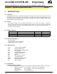
ALLGON SYSTEM AB - Proprietary Technical Specification for PCS Tower Top Power Amplifier [Allgon 9256] Rev.pA0 Preliminary - Subjected to change without notice 1 1.1 INTRODUCTION PURPOSE This document describes the Technical specification for the Allgon Tower Top Power Amplifier for the PCS 1900 cellular band. The product number specified in the header has different variants available. These variants have different bandwidths, gain and options.
ALLGON SYSTEM AB - Proprietary Technical Specification for PCS Tower Top Power Amplifier [Allgon 9256] Preliminary - Subjected to change without notice Mounting: Rev.pA0 Acc. to chapter 5.3 The parameters specified are guaranteed over the warranty time. ! Typical parameters: All typical parameters are considered to be measured at an ambient temperature of 20 °C, and air pressure of 1013 mbar, after 30 min warm up, unless otherwise stated. The TTPA is designed for an operating life exceeding 10 years.
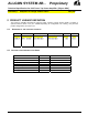
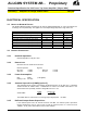
ALLGON SYSTEM AB - Proprietary Technical Specification for PCS Tower Top Power Amplifier [Allgon 9256] Rev.pA0 Preliminary - Subjected to change without notice 2 PRODUCT VARIANT DEFINITION The TTPA are available with different frequency bands, together covering all PCS bands. A number of optional functions (listed in 2.2) are available depending on configuration. The existing, and preferred product configurations, are listen in 2.1. 2.1 DEFINITION OF THE AVAILABLE VARIANTS Variant 9228.01 9228.
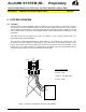
ALLGON SYSTEM AB - Proprietary Technical Specification for PCS Tower Top Power Amplifier [Allgon 9256] Rev.pA0 Preliminary - Subjected to change without notice 3 SYSTEM OVERVIEW 3.1 GENERAL The PCS Tower Top Power Amplifier (TTPA) is intended for use at sites where it is necessary to improve the coverage area. The TTPA boosts both the receive-path signal and the transmit power from one TRx in order to preserve site link balance. TX and RX signal paths are separated by means of duplexers.
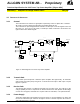
ALLGON SYSTEM AB - Proprietary Technical Specification for PCS Tower Top Power Amplifier [Allgon 9256] Rev.pA0 Preliminary - Subjected to change without notice 3.2 PRINCIPLE OF OPERATION 3.2.1 General The TTPA has the RX and the TX signal paths separated by means of duplex filter or isolators. All circuitry for power supply and supervision are included inside the unit. The TTPA has two ports designated BTS and ANT. The BTS port carries the signals to/from the BTS rack (e.g. TX-in, RX-out, DC-power).
ALLGON SYSTEM AB - Proprietary Technical Specification for PCS Tower Top Power Amplifier [Allgon 9256] Rev.pA0 Preliminary - Subjected to change without notice 3.2.5 Supervision A number of parameters are constantly supervised. TX Power Amplifier: Output power, VSWR (when input power within specified limits), transistor currents, voltages, temperature and power supply. VSWR supervision optional. RX LNA: Transistor currents and power supply.
ALLGON SYSTEM AB - Proprietary Technical Specification for PCS Tower Top Power Amplifier [Allgon 9256] Preliminary - Subjected to change without notice Rev.pA0 **** Optional function, not supported in all variant.
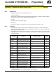
ALLGON SYSTEM AB - Proprietary Technical Specification for PCS Tower Top Power Amplifier [Allgon 9256] Rev.pA0 Preliminary - Subjected to change without notice ELECTRICAL SPECIFICATION 3.3 ABSOLUTE MAXIM UM RATINGS The Absolute Maximum Rating is defined as the value of applied signal/power etc. that is guaranteed not to damage the unit permanently. This applies over the full operating temperature range of the unit. Parameter 3.1.1 Input DC Voltage (low imp. Source) 3.1.2 Reverse Input DC Voltage 3.1.
ALLGON SYSTEM AB - Proprietary Technical Specification for PCS Tower Top Power Amplifier [Allgon 9256] Rev.pA0 Preliminary - Subjected to change without notice 3.4.6 Total Feeder DC Resistance and Maximum Feeder Length Maximum length: 250 m (833 ft) Maximum feeder DC resistance: 2Ω Measured between the inner and outer connector with the other feeder end short circuited. **Note: Only valid when using feeder cable for DC-feed. 3.4.
ALLGON SYSTEM AB - Proprietary Technical Specification for PCS Tower Top Power Amplifier [Allgon 9256] Rev.pA0 Preliminary - Subjected to change without notice 3.5.6 TX Gain Tolerance Measured with AGC in operation. Nominal gain ± 0.5 dB 3.5.7 TX Gain Ripple Ripple is defined as [MaxGain(inband) - MinGain(inband)] Max: 3.5.8 1 dB TX AGC Operation The AGC system continuously holds the TX-gain at nominal value. If the system fails to regulate the power a PA-fail alarm is generated.
ALLGON SYSTEM AB - Proprietary Technical Specification for PCS Tower Top Power Amplifier [Allgon 9256] Preliminary - Subjected to change without notice 3.5.11 Rev.pA0 TX Bypass Loss (option 7) TX bypass function is optional. Measured from ANT to BTS port Typ. 2.0 dB Max: 2.6 dB 3.5.12 TX Redundancy & Bypass Operation In the event of failure of one of the transistors in the power amplifier the gain will drop by approx. 6dB. In this condition a TX-minor alarm will be generated.
ALLGON SYSTEM AB - Proprietary Technical Specification for PCS Tower Top Power Amplifier [Allgon 9256] Rev.pA0 Preliminary - Subjected to change without notice 3.6.8 RX Stability The RX-amplifier is unconditionally stable for all loads at input and output of the TTPA. 3.6.9 RX Redundancy In the event of failure of one of the transistors in the balanced LNA the gain will drop by approx. 6dB. An RX-minor alarm will be generated. If both transistors fail, an RX-major alarm will be generated. 3.
ALLGON SYSTEM AB - Proprietary Technical Specification for PCS Tower Top Power Amplifier [Allgon 9256] Preliminary - Subjected to change without notice 3.8.6 Rev.pA0 Inrush Current Measured at power on with nominal supply voltage. Max peak: 15A Max after 10ms: 3A 4 MECHANICAL SPECIFICATION 4.1 PHYSICAL PARAM ETERS 4.1.1 Height 350 mm 4.1.2 (±20mm) Width 220 mm 4.1.3 (±20mm) Depth 230 mm 4.1.4 (±20mm) Volume 3 17 dm 4.1.5 Weight - Clamping Unit 3 kg 4.1.
ALLGON SYSTEM AB - Proprietary Technical Specification for PCS Tower Top Power Amplifier [Allgon 9256] Preliminary - Subjected to change without notice 4.2.1 Rev.pA0 BTS Connector 7/16 Female 4.2.2 ANT Connector 7/16 Female 4.2.3 Earthing Earthing stud: 4.2.4 M8 x 15mm DC Connector (option 2) Optional DC connector for separate DC, see 2.2 Type: Binder series 623 , 6 poles, male 4.2.5 Alarm Connector (option 3) Optional alarm connector, see 2.2 Type: Binder series 623 , 12 poles, male 4.2.
ALLGON SYSTEM AB - Proprietary Technical Specification for PCS Tower Top Power Amplifier [Allgon 9256] Preliminary - Subjected to change without notice Rev.pA0 5 ENVIRONMENTAL SPECIFICATION 5.1 OPERATING CONDITIONS ( Conditions: The unit mounted in free air, DC power applied at all times.) 5.1.1 Ambient Air Temperature Full Performance Max: Min: 5.1.
ALLGON SYSTEM AB - Proprietary Technical Specification for PCS Tower Top Power Amplifier [Allgon 9256] Preliminary - Subjected to change without notice 5.2.2 Relative Humidity Max: Min: 5.2.3 2°C/min (ambient) Air Pressure Max: Min: 5.2.6 3 30 g/m 3 0.26 g/m Rate of Temperature Change Max: 5.2.5 100 % 8% Absolute Humidity Max: Min: 5.2.4 106 kPa 50 kPa Vibration According to: 5.2.7 ETS 300 019-2-2 class T2.3 ETS 300 019-2-1 class T1.
ALLGON SYSTEM AB - Proprietary Technical Specification for PCS Tower Top Power Amplifier [Allgon 9256] Preliminary - Subjected to change without notice Rev.pA0 Note: the calculated MTBF gives a very conservative value. Especially when the components MTBF is based on the default data specified in MIL-HDBK-217F and not from an accelerated life time test. If such data was available on every component then a result close to the field proven MTBF could be calculated. 6.