
User's Manual


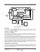

Table Of Contents

G3L-2129-140 MCPA Functional Description
044-05369 Rev A 1-3
Preamplifier
The carrier (RF In) is applied to the input port of the MCPA and fed to the preamplifier stage where it is amplified
using two stages of class A mode amplifiers. The output of the preamplifier is split into two paths, one to the
main amplifier and one to the error amplifier.
Main and Error Amplifiers
The main amplifier provides the balance of gain and power in the 2110 MHz to 2170 MHz frequency band,
using class AB amplification for maximum efficiency. The error amplifier and feed forward loops correct signal
non-linearities introduced by the class AB main amplifier.
In the error amplifier, which operates in class A mode, the RF signal is coupled to an attenuator and phase
shifter in the first feed-forward loop, phase shifted by 180 degrees and then amplified in the premain amplifier.
The output from the pre-main amplifier is fed to the class AB main amplifier and then sampled using a coupler.
The signal (RF sample) is combined with the main input signal and input to the second feed-forward loop.
There, the RF sample is attenuated, phase shifted 180 degrees, and fed to the error amplifier where it is
amplified to a level identical to the sample output from the main amplifier. The output from the error amplifier
(Error Out) is coupled back and added to the output from the main amplifier, with the control loops continuously
making adjustments to cancel out any distortion in the final output signals.
Feed-forward Loop Control Circuits
The primary function of the first loop is to amplify the carrier signals and isolate an error signal for the second
loop. It does this by amplifying the carrier signals and isolating an error signal which is passed to the second
loop. The first loop control section phase shifts the main input signals by 180 degrees and constantly monitors
the output for correct phase and gain.
Figure 1-2 MCPA Functional Block Diagram
Preamp
Delay
Second Loop
Phase and Gain
Error
Amplifier
First Loop
Phase and Gain
Reflected
Power
(VSWR)
RF Out
Pilot Tone
Generator
RF Sample
Forward Power / Pilot Tone Detect
RF In
Premain
Amplifier
Error Out
Delay
Filter
Main
Amplifier
System
Faults
Front Panel
LED
Status
ON/OFF/RESET
Switch
Control
VDC VDC VDCVDC
+27 VDC
User
Interface
Pilot Tone
Controller
First Loop
Detection
FIRST LOOP
SECOND LOOP
First Loop
Control
Second Loop
Control
-5
+5+9+15
DRAFT