
User's Manual


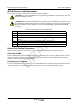


Table Of Contents

044-05369 Rev A 3-1
Chapter 3
Installation
Introduction
This chapter contains unpacking, inspection, startup and installation procedures for the G3L-2129-140 Multi-
Carrier Power Amplifier (MCPA).
❑ Review this chapter prior to equipment installation.
❑ Review any government and local codes applicable to this installation.
❑ Read the instructions in this Chapter and Chapter 4 before operating the equipment.
Unpacking and Inspection
Perform the steps in Table 3-1 to unpack and inspect the MCPA.
Damaged Equipment
If the MCPA is damaged, a claim should be filed with the carrier when the extent of any damage is assessed.
Contact the factory for a return material authorization (RMA). Refer to Chapter 4 for the return procedure.
Air Conditioning Requirement
The MCPA generates 2770 BTUs of heat at 36 amps, 27 VDC and 140 watts average RF power output. The
MCPA operates within the extended low temperature and high temperature environments as listed in
Chapter 5.
MCPA Installation Instructions
CAUTION: Do not slam the MCPA into the system subrack during installation. Using excessive
force can damage the MCPA interface connector.
The modular MCPA can be installed in a variety of systems. All system connections to the MCPA are made
through the MCPA rear connector, no additional wiring is required. Perform the steps in Table 3-2 to install the
MCPA. Refer to Figure 3-1 MCPA Quarter-turn fasteners and Connectors for quarter-turn fastener position and
switch location.
Table 3-1 Unpacking steps
Step Action
1
Carefully open container and remove MCPA.
2
Visually inspect MCPA for damage that may have occurred during shipment.
Check for evidence of water damage, bent or warped chassis, loose screws or
nuts, or extraneous packing material in connectors. If possible, inspect equipment
in the presence of the delivery person.
3
If possible, retain all packing material that can be reused for repackaging
components.
DRAFT