User's Manual
Manuals
Brands
Powerwave Technologies Manuals
Electronics
Multi-carrier RF Power Amplifier
11
12
13
14
15
16
17
18
19
20
Table Of Contents
Chapter 1 Product Description
Introduction
Scope of Manual
Product Description
Functional Description
Figure 1-1 MCPA Front and Rear Views
Figure 1-2 MCPA Functional Block Diagram
Preamplifier
Main and Error Amplifiers
Feed-forward Loop Control Circuits
Pilot Tone Generator
Controller
Cooling
Power Distribution
Chapter 2 Controls and Indicators
Introduction
MCPA Controls and Indicators
Figure 2-1 MCPA Controls and Indicators
Table 2-1 LED Indicators
MCPA Alarms
Table 2-2 MCPA Alarm States
MCPA Connectors
Figure 2-2 MCPA Interface Connector
Table 2-3 MCPA Connector Pin Assignments
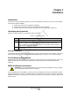
Chapter 3 Installation
Introduction
Unpacking and Inspection
Table 3-1 Unpacking steps
Damaged Equipment
Air Conditioning Requirement
MCPA Installation Instructions
Table 3-2 MCPA Installation Steps
Figure 3-1 MCPA Quarter-turn fasteners and Connectors
Initial Start-up and Operating Procedures
Table 3-3 MCPA Start-up Steps
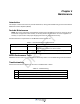
Chapter 4 Maintenance
Introduction
Periodic Maintenance
Table 4-1 Periodic Maintenance Requirements
MCPA Performance Tests
Troubleshooting
Table 4-2 Troubleshooting
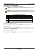
MCPA Removal and Replacement
Table 4-3 MCPA Removal and Replacement
Return For Service Procedures
Obtaining An RMA
Repackaging for Shipment
Chapter 5 Specifications
Multi-Carrier Power Amplifier Specifications
Table 5-1 Specifications
MCPA Contr
ols and Indica
tors
G3L-212
9-140 MCPA
2-4
044-053
69 Rev A
This pag
e inten
tional
ly left b
lank.
DRAFT
1
...
...
12
13
14
15
16
...
...
20