
User's Manual

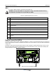


Table Of Contents
- Safety
- Electrostatic Discharge (ESD)
- Chapter 1 Product Description
- Introduction
- Scope of Manual
- Overview
- Figure 1-1 PowerwaveWRH Radio Head
- Chassis Design
- Wideband Amplifier PCBA (WBA)
- Multi-Carrier Power Amplifier PCBA (MCPA)
- Distribution PCBA (DIA)
- Figure 1-2 DIA PCBA
- Control Unit PCBA (CU)
- Figure 1-3 CU PCBA
- Low Noise Amplifier (LNA)
- Figure 1-4 LNA
- Duplex Filter (DPX)
- Fiber Optic Unit (FOU)
- Figure 1-5 FOU in Nexus FT
- Fiber Optic Node (FON)
- Power Supply Unit (PSU)
- Remote Control Unit (RCU)
- Alarm Interface PCBA (ALI) and Remote Control Interface PCBA (RCI)
- Figure 1-6 Nexus FT Sub Unit Locations
- Figure 1-7 Fiber Optic Star Configuration
- Figure 1-8 Multi-operator System
- Chapter 2 Controls, Indicators and Connectors
- Chapter 3 Installation
- Chapter 4 Maintenance
- Chapter 5 Specifications
- Appendix A Block Diagrams

Diversity Nexus FT
A-2 044-05251 Rev B
Diversity
Figure A-2 illustrates the diversity block diagram configuration of the WRH. With diversity installed, there are
two paths on the UL instead of one. This requires an additional FON for the added receive path signal. Signal
flow is identical to the non-diversity version with the MCPA on the DL and LNAs on the UL providing the
additional amplification out of and into the WBA.
Figure A-2 WRH Block Diagram - Diversity
WDM
DX
DX
DPX
WBA
DL
LNA
MCPA
To/From
OCM or
BMU
RCU
RCI
PSU
CU
FON
ALI
To
External
alarms
FOU
DX
LNA
DPX
DPX
WBA
LNA
MCPA
LNA
DPX
UL
DL
FON
1900 MHz
TX0/RX0
850 MHz
TX0/RX0
850 MHz
RX1
1900 MHz
RX1
UL
UL
UL