
User's Manual

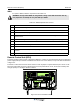


Table Of Contents
- Safety
- Electrostatic Discharge (ESD)
- Chapter 1 Product Description
- Introduction
- Scope of Manual
- Overview
- Figure 1-1 PowerwaveWRH Radio Head
- Chassis Design
- Wideband Amplifier PCBA (WBA)
- Multi-Carrier Power Amplifier PCBA (MCPA)
- Distribution PCBA (DIA)
- Figure 1-2 DIA PCBA
- Control Unit PCBA (CU)
- Figure 1-3 CU PCBA
- Low Noise Amplifier (LNA)
- Figure 1-4 LNA
- Duplex Filter (DPX)
- Fiber Optic Unit (FOU)
- Figure 1-5 FOU in Nexus FT
- Fiber Optic Node (FON)
- Power Supply Unit (PSU)
- Remote Control Unit (RCU)
- Alarm Interface PCBA (ALI) and Remote Control Interface PCBA (RCI)
- Figure 1-6 Nexus FT Sub Unit Locations
- Figure 1-7 Fiber Optic Star Configuration
- Figure 1-8 Multi-operator System
- Chapter 2 Controls, Indicators and Connectors
- Chapter 3 Installation
- Chapter 4 Maintenance
- Chapter 5 Specifications
- Appendix A Block Diagrams

Remote Control Unit (RCU) Nexus FT
4-8 044-05251 Rev B
WRH
To replace a WRH, follow the steps listed in the Table 4-5.
.
Remote Control Unit (RCU)
The RCU provides remote control of Powerwave WRHs. It contains an integrated mobile phone, modem and
power supply backup. The RCU is installed in the bottom front of the cabinet, on top of the PSU as illustrated
in Figure 4-2.
The RCU is connected to P130 on either an RCI or FON. A jumper is required between pins 1 and 2 on the
R
CI if the P130 ca
ble connector is disconnected. If a main power failure occurs, the unit has a battery with
enough capacity for sending a number of alarms.
Figure 4-2 RCU in the WRH cabinet
WARNING: A fully loaded WRH can weigh 96lbs. Lifting of the WRH should be done by
two people. Do not attempt to carry the WRH up a ladder.
Table 4-5 WRH Replacement Procedure
Step Action
1 Loosen all four locking screws on front of cabinet
2 Open WRH door and secure
3 Disconnect main power plug from PSU
4 Verify all external cables connected to WRH are labeled before disconnecting, then disconnect all
e
xternal cables
5 Remove mounting screws from bottom legs of WRH and loosen mounting screws in top legs
6 Close and secure door
7 Lift the WRH off of mount hinges
8 Replace WRH in reverse order
9 Connect PC to OM Online port and verify configuration. For Fiber Optic installations, verify IP
a
ddress
10 Close WRH d
oor and secure
MS
DPX
ANT
TEST
DC
-30 dB
-20 dB
MS
DPX
ANT
TEST
DC
-30 dB
-20 dB
ALLGO N INNOVATIO N
SWEDEN M105 R6
1
PARKING
FOR W5
W5
8
P27
W6B 1 0
1
P33
ALARM
P23
LNA
UP-LINK
P32
MODEM
A
U
X
1
P28
DOOR
5
9
6
1
1
16
1
1
M
-
>
S
P11
P34
8
9
15
P26
15 16
S
-
>
M
1
2
3
89
P
3
6
5
X0A
X0B
2
V2
1
16
P12 P13
1
1
1
16
16
16
P4
P5
P6
c
b
a
c
b
a
c
b
a
c
b
a
1P232
1
b
a
1
16P3
16
1
16
P14
1
V1
1
1
1
1
1
4
6
1
15
6
9
15
2
16
1
2
4
5
8
5
P35
P21
PSU
6
10
P31
PC
P29
P24
P25
GND
7
6V6
LNA
DOWN-LINK
LED
P22
1
2
POWER SUPPLY UNIT
RCU