
User's Manual

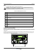


Table Of Contents
- Safety
- Electrostatic Discharge (ESD)
- Chapter 1 Product Description
- Introduction
- Scope of Manual
- Overview
- Figure 1-1 PowerwaveWRH Radio Head
- Chassis Design
- Wideband Amplifier PCBA (WBA)
- Multi-Carrier Power Amplifier PCBA (MCPA)
- Distribution PCBA (DIA)
- Figure 1-2 DIA PCBA
- Control Unit PCBA (CU)
- Figure 1-3 CU PCBA
- Low Noise Amplifier (LNA)
- Figure 1-4 LNA
- Duplex Filter (DPX)
- Fiber Optic Unit (FOU)
- Figure 1-5 FOU in Nexus FT
- Fiber Optic Node (FON)
- Power Supply Unit (PSU)
- Remote Control Unit (RCU)
- Alarm Interface PCBA (ALI) and Remote Control Interface PCBA (RCI)
- Figure 1-6 Nexus FT Sub Unit Locations
- Figure 1-7 Fiber Optic Star Configuration
- Figure 1-8 Multi-operator System
- Chapter 2 Controls, Indicators and Connectors
- Chapter 3 Installation
- Chapter 4 Maintenance
- Chapter 5 Specifications
- Appendix A Block Diagrams

Nexus FT Field Replaceable Units
044-05251 Rev B 4-7
PSU
To replace a PSU, follow the steps listed in Table 4-4. For details on cables and connectors, see Chapter 2.
Figure 4-1 PSU Cable, Switch and Lable locations
Table 4-4 PSU Replacement Procedure
Step Action
1 Loosen all four locking screws on front of cabinet
2 Open WRH door and secure
3 Disconnect main power plug from PSU(Location 1 shown in Figure 4-1)
4 Disconnect power cable bundle from PSU(Location 2 shown in Figure 4-1)
5 Loosen but do not remove screws securing PSU using a 5mm Allen key and remove PSU (Location 3
sh
own in Figure 4-1)
6 On new AC power supply, if used, set input voltage switch on PSU to correct input voltage -- 115 VAC
or 230 VAC (Location 4 s
hown in Figure 4-1)
7 On new DC power supply, if used, verify that the supply voltage is 24 VDC or 48 VDC as stated on
label on PSU (Locat
ion 5 shown in Figure 4-1)
8 Set new PSU to correct output supply voltage (27 VDC) by moving wire connection plug as illustrated
on label on PSU (Loc
ation 6 shown in Figure 4-1)
9 Mount new PSU with all four fixing screws (Location 3 shown in Figure 4-1)
10 Connect PSU to DIA PCBA (Location 2 shown in Figure 4-9) with cable marked VE007 98/1. This
cable must be u
sed in all situations. If only one connection is available on DIA PCBA, the second
connector may be tied out of the way with a cable tie
11 Insert power cord (AC power supply) or connect DC power cable brown wire (Europe) or black wire
(US) to
positive (+) pole a
nd blue wire (Europe) or white wire (US) to negative (-) pole (DC power
supply)
12 Close WRH door and secure with four locking screws on front of cabinet
4
5
6