
User's Manual


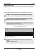
Table Of Contents
- Safety
- Electrostatic Discharge (ESD)
- Chapter 1 Product Description
- Introduction
- Scope of Manual
- Overview
- Figure 1-1 PowerwaveWRH Radio Head
- Chassis Design
- Wideband Amplifier PCBA (WBA)
- Multi-Carrier Power Amplifier PCBA (MCPA)
- Distribution PCBA (DIA)
- Figure 1-2 DIA PCBA
- Control Unit PCBA (CU)
- Figure 1-3 CU PCBA
- Low Noise Amplifier (LNA)
- Figure 1-4 LNA
- Duplex Filter (DPX)
- Fiber Optic Unit (FOU)
- Figure 1-5 FOU in Nexus FT
- Fiber Optic Node (FON)
- Power Supply Unit (PSU)
- Remote Control Unit (RCU)
- Alarm Interface PCBA (ALI) and Remote Control Interface PCBA (RCI)
- Figure 1-6 Nexus FT Sub Unit Locations
- Figure 1-7 Fiber Optic Star Configuration
- Figure 1-8 Multi-operator System
- Chapter 2 Controls, Indicators and Connectors
- Chapter 3 Installation
- Chapter 4 Maintenance
- Chapter 5 Specifications
- Appendix A Block Diagrams

Troubleshooting Nexus FT
4-2 044-05251 Rev B
Ceasing PSU2 in the cover works properly again. Ceasing is sent if the
PSU2 works at start-up, and there is a corresponding critical
PSU2 alarm logged in the Events Log. The WRH will restart when
the power is back and this alarm will be sent
Power FON Error The FON 10 Volt charger voltage is below limit. Suggested
remedy: Replac
e the FON
Ceasing The cause of the alarm has ceased
2 WRH restart CU None Power on start, or user ordered reboot. Logged to indicate a
normal power up
, or a restart ordered by the operator
Warning Software error restart, 1st – 7th time. Restart 1st to 7th time during
a 14 day period. The co
unter is reset every 14th day, counted
from power up
Error Software error restart 8th – 10th time. Restart 8th to 10th time
d
uring the 14 day
period. At the 11th time, the SW bank will be
blocked and not used anymore until a user ordered reset is
performed, or power is switched off/on
3 Mains
breakdown
External Crit
ical The mains power is gone. Used with an external relay indicating
mains breakdown. The external relay should be connected to
External Alarm 1 and the WRH configured to indicate this alarm. If
no relay is used, a mains breakdown will be reported as a PSU
fault
Ceasing The mains power is back. Sent if there is a corresponding critical
mains breakdown alarm logged in the Events Log. The WRH will
restart when the power is back
4 Alarm reset CU None Alarm reset by the user. All alarms are reset. The cause of the
a
larm will be
re-evaluated and reported, if still active
5 Local bus
error
WBA #,
MCPA#
Error Error when com
municating on the bus. The CU has no contact
with the WBA, or MCPA PCBA, which is taken out of service
6 Main bkd w
backup
External Error Used to
indicate that the mains is no longer available. WRH is
powered by external battery backup unit. Suggested remedy:
Check the mains power
Ceasing The cause of the alarm has ceased
7 Err in AD-
converter
Warning The ana
log-to-digital converter on the CU PCBA does not give
reliable values
8 New unit
detected
None Compared
to the last power on, the CU has recognized at least
one additional hardware unit
9 Inst. unit lost Error Compared to the last power on, the CU lacks at least one
hardware unit
10 EEPROM
erro
r
CU Error EEP read or write fail
. Data cannot be written or read from the
EEPROM on the CU PCBA. User parameters are stored in the
EEPROM
11 Log memory
fau
lt
Error Log memory
fault. Indicates that the log memory on the CU PCBA
is faulty. The WRH will not work. Not available in all CU software
versions
Table 4-2 Alarm Troubleshooting (Continued)
ID Alarm Text Alarm Unit Alarm Description