
User's Manual
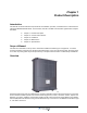


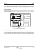


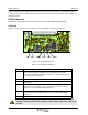


Table Of Contents
- Safety
- Electrostatic Discharge (ESD)
- Chapter 1 Product Description
- Introduction
- Scope of Manual
- Overview
- Figure 1-1 PowerwaveWRH Radio Head
- Chassis Design
- Wideband Amplifier PCBA (WBA)
- Multi-Carrier Power Amplifier PCBA (MCPA)
- Distribution PCBA (DIA)
- Figure 1-2 DIA PCBA
- Control Unit PCBA (CU)
- Figure 1-3 CU PCBA
- Low Noise Amplifier (LNA)
- Figure 1-4 LNA
- Duplex Filter (DPX)
- Fiber Optic Unit (FOU)
- Figure 1-5 FOU in Nexus FT
- Fiber Optic Node (FON)
- Power Supply Unit (PSU)
- Remote Control Unit (RCU)
- Alarm Interface PCBA (ALI) and Remote Control Interface PCBA (RCI)
- Figure 1-6 Nexus FT Sub Unit Locations
- Figure 1-7 Fiber Optic Star Configuration
- Figure 1-8 Multi-operator System
- Chapter 2 Controls, Indicators and Connectors
- Chapter 3 Installation
- Chapter 4 Maintenance
- Chapter 5 Specifications
- Appendix A Block Diagrams

Overview Nexus FT
1-6 044-05251 Rev B
Splitters (OSPs) in the Nexus FTs, the distribution net can be built up with a combination of star and daisy-chain
connections using double or single fiber.
Figure 1-7 Fiber Optic Star Configuration
Multi-Operator Configurations
Multi-operator systems require the use of Point of Interconnect (POI) units and OCMs as illustrated in Figure
1-8. In this simple example, two operators have two sectors each. Each sector is connected to a POI and then
to a RCM. The RCM is interconnected with an OCM via coaxial cables. The combined DL and UL signals are
converted to optical signals in the OCM and then distributed to the Nexus FTs-V.
Figure 1-8 Multi-operator System
BMU WRH
WRH
WRH
WRH
BTS
RF
Operator 1
Operator 2
Sector 1
Sector 1
Sector 2
Sector 2
OCM
OCM-POI
BTS-POI
BTS-POI
BTS-POI
BTS-POI
OCM-POI