
User's Manual
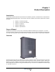


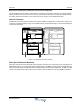


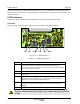


Table Of Contents
- Safety
- Electrostatic Discharge (ESD)
- Chapter 1 Product Description
- Introduction
- Scope of Manual
- Overview
- Figure 1-1 PowerwaveWRH Radio Head
- Chassis Design
- Wideband Amplifier PCBA (WBA)
- Multi-Carrier Power Amplifier PCBA (MCPA)
- Distribution PCBA (DIA)
- Figure 1-2 DIA PCBA
- Control Unit PCBA (CU)
- Figure 1-3 CU PCBA
- Low Noise Amplifier (LNA)
- Figure 1-4 LNA
- Duplex Filter (DPX)
- Fiber Optic Unit (FOU)
- Figure 1-5 FOU in Nexus FT
- Fiber Optic Node (FON)
- Power Supply Unit (PSU)
- Remote Control Unit (RCU)
- Alarm Interface PCBA (ALI) and Remote Control Interface PCBA (RCI)
- Figure 1-6 Nexus FT Sub Unit Locations
- Figure 1-7 Fiber Optic Star Configuration
- Figure 1-8 Multi-operator System
- Chapter 2 Controls, Indicators and Connectors
- Chapter 3 Installation
- Chapter 4 Maintenance
- Chapter 5 Specifications
- Appendix A Block Diagrams

Nexus FT Overview
044-05251 Rev B 1-5
Alarm Interface PCBA (ALI) and Remote Control Interface PCBA (RCI)
The ALI handles alarms and alarm communication. It is replace with an RCI if
an RCU is used and provides an
interface between the CU and an RCU for remote communication via modem. The RCI also handles alarms
and alarm communication. Either unit is located in the lower left part of the shielded DIA frame.
Sub Unit Locations
The MCPA is located at positions 3 and 4 in the cabinet. A WRH is equipped for one band in the cabinet and,
if required, an additional band in a high cover. PCBA positions are illustrated in Figure 1-6 and a block diagram
is located in Appendix A.
Figure 1-6 Nexus FT Sub Unit Locations
Fiber Optic Distribution Networks
Fiber optic networks are setup identically to data networks. Nexus FTs are connected in a star configuration as
illustrated in Figure 1-7. In this example, a Base Station Master Unit (BMU) is fed by a BTS via an RF cable. An
Optical Converter Module (OCM) could also be used depending on the system configuration. The BMU or OCM
contain three FONs and provide continuity to the FONs in the four Nexus FTs. By using WDMs and Optical
1234
LNA - UL
PSU
(RCU)
DPX
CUALI/RCI
WBA
DL/UL
FOU
MCPA DL
5678
PSU
(RCU)
DPX
CUALI/RCI
WBA
DL/UL
FOU
MCPA DL
FON FON