
User's Manual
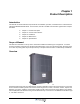


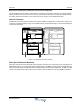


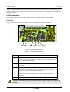


Table Of Contents
- Safety
- Electrostatic Discharge (ESD)
- Chapter 1 Product Description
- Introduction
- Scope of Manual
- Overview
- Figure 1-1 PowerwaveWRH Radio Head
- Chassis Design
- Wideband Amplifier PCBA (WBA)
- Multi-Carrier Power Amplifier PCBA (MCPA)
- Distribution PCBA (DIA)
- Figure 1-2 DIA PCBA
- Control Unit PCBA (CU)
- Figure 1-3 CU PCBA
- Low Noise Amplifier (LNA)
- Figure 1-4 LNA
- Duplex Filter (DPX)
- Fiber Optic Unit (FOU)
- Figure 1-5 FOU in Nexus FT
- Fiber Optic Node (FON)
- Power Supply Unit (PSU)
- Remote Control Unit (RCU)
- Alarm Interface PCBA (ALI) and Remote Control Interface PCBA (RCI)
- Figure 1-6 Nexus FT Sub Unit Locations
- Figure 1-7 Fiber Optic Star Configuration
- Figure 1-8 Multi-operator System
- Chapter 2 Controls, Indicators and Connectors
- Chapter 3 Installation
- Chapter 4 Maintenance
- Chapter 5 Specifications
- Appendix A Block Diagrams

Overview Nexus FT
1-2 044-05251 Rev B
Nexus FTs are microprocessor controlled with alarm and operational status LEDs visible on the front cover.
Cooling is provided through convection heat dissipation. Operational parameters, such as gain and power
levels are set using a PC running Powerwave OM-Online software which communicates with the Nexus FTs
either locally or remotely via modem. Remote operation can be performed via PSTN or a GSM net. The
Operation and Maintenance System (OMS) provides for Network Operations Center (NOC) configuration and
alarm monitoring.
Nexus FTs can be configured in many combinations depending on the wireless system, single or double
s
ystem operatio
n, and output power. The following paragraphs provide a description of the different models of
Nexus FTs available.
The WRH is a fiber fed system designed to provide a high output power level and comes equipped with a MCPA
in the downlink path. T
he MCPA restricts the number of bands to one in the cabinet and one additional band if
a high cover is used. The MCPA is located in the cabinet and is supplied from the existing PSU.
Chassis Design
The WRH is housed in a cast aluminium waterproof chassis, class NEMA4 / IP65, approved for outdoor use but
is also suited for indoor installations. The chassis consists of a cabinet and a cover attached with hinges. The
cabinet contains the WRH circuitry. The cover comes as either a low or high version. The high cover can be
used as an empty cover or be equipped as a part of the WRH or an independent WRH unit. A WRH with a high
cover that is equipped as two independent units can, for example, be equipped for channel selective operation
in the cabinet and band selective operation in the cover.
Inside the Nexus FT, a number of amplifier PCBAs are individually shielded and located under a metal cover
t
hat can be opened outward. T
hese PCBAs are of different types depending on the supported system.
Sub Unit Overview
A number of amplifier PCBAs are individually shielded and located under a metal cover inside the Nexus FT.
This cover can be opened outward for access. These amplifier PCBAs are of different types depending on the
supported system. All of the Nexus FTs are built up with a number of sub units which are described in the
following sections.
Wideband Amplifier PCBA (WBA)
Nexus FTs can handle multiple carriers over a wide band. Each band requires one WBA for the uplink and
downlink, and one asso
ciated PA or MCPA for the downlink. The cabinet can be equipped with up to two WBAs
along with two PAs supporting two bands or one MCPA supporting one band. Positions 1 and 3, shown in
Figure 1-6, are assigned for a WBA.
Multi-Carrier Power Amplifier
PCBA (MCPA)
The MCPA is
used to amplify the output signal from the WBA. Each MCPA can handle one band in the downlink
direction. It req
uires an extra heat sink element on the outside of the cabinet or high cover to dissipate the heat
generated. The MCPA occupies positions 2 through 4 in the cabinet and 6 through 8 in a high cover, as shown
in Figure 1-6.